
Subscribe to Our Youtube Channel
Related Manuals for BBH SCU Series


Summary of Contents for BBH SCU Series
- Page 1 Programming manual SCU-series Programming manual For the SCU-series With SafePLC HB-37500-820-10-12F-EN SCU Programming manual Page 1 of 252 Status: 19.03.2021...
- Page 2 Responsible for the compilation of the documents: Gerhard Bauer, Managing Director BBH Products This document is subject to German copyright. Copying, processing, and any kind of use beyond the limits of copyright require the written consent of the respective author or creator.
-
Page 3: Table Of Contents
Programming manual SCU-series 1. Tables 1.1. Table of contents Tables ......................3 1.1. Table of contents ....................3 1.2. Register of illustrations ..................9 Basic information ..................15 2.1. Important information for use ................15 2.2. Scope of delivery .....................15 2.3. Terms ......................15 2.4. - Page 4 Programming manual SCU-series 4.3.2.3. Automatic hide ....................31 4.3.3. Title bar ......................32 4.3.4. Start menu .......................33 4.3.5. Menu of the ribbon ...................35 4.3.5.1. Start .........................36 4.3.5.2. Windows ......................37 4.3.5.3. Filters .......................40 4.3.6. Status bar ......................41 4.3.7. Mouse commands and keyboard commands ...........41 4.3.7.1.
- Page 5 Programming manual SCU-series 4.3.15. Global search ....................58 4.3.15.1. Search settings ....................59 4.3.15.2. Quickly jump to an element ................59 4.3.16. Print .........................60 4.3.17. Settings ......................62 4.3.18. Auto Recovery ....................64 4.3.19. Information concerning the program..............65 4.3.20. Window “User Rights Dialog” ................65 4.3.20.1. Tab “Users”...
- Page 6 Programming manual SCU-series 4.6.11.1. Diagnosis process in the function block diagram ..........100 4.6.11.1.1. Diagnosis in the work surface ................ 100 4.6.11.1.2. Diagnosis in the Function Block tab ............... 100 4.6.12. Scope Onlinediagnostics ................103 4.6.12.1. Procedure of a measuring in the range ............106 4.6.12.2.
- Page 7 Programming manual SCU-series 4.13.2. Input elements ....................146 4.13.2.1. List of input elements ..................149 4.13.2.2. Listing of the startup types via the “Enable” button ......... 154 4.13.3. Output blocks ....................156 4.13.3.1. List of output elements ................... 157 4.13.4. Encoder combinations ...................
- Page 8 Programming manual SCU-series 5.6.5. Monitoring functions ..................237 5.6.5.1. Cascading ...................... 237 5.6.5.2. Axis groups ....................238 5.7. Safety-raleted verification ................240 5.7.1. The validation process ................... 240 Failure and troubleshooting ..............241 List of abbreviations ................242 Appendix....................244 8.1.
-
Page 9: Register Of Illustrations
Programming manual SCU-series 1.2. Register of illustrations Figure 1: EtherCAT network ....................18 Figure 2: FSoE network .......................20 Figure 3 user registration .....................28 Figure 4 structure of the application window ................29 Figure 5 "window" tab, layout reset ..................30 Figure 6 Personalize the application window by docking ............30 Figure 7 Docking .........................31 Figure 8 Automatic hide .......................31 Figure 9 context menu ......................32... - Page 10 Programming manual SCU-series Figure 32 view message window ..................57 Figure 33 Message window with search field ...............57 Figure 34 message window with context menu ..............58 Figure 35 "Global search" ....................58 Figure 36 Define search settings ..................59 Figure 37 Tab “Print Preview” .....................60 Figure 38 User Path tab in the Settings user window ............62 Figure 39 “Lbrary”...
- Page 11 Programming manual SCU-series Figure 66 SDC-parameters ....................86 Figure 67 SDC axes ......................87 ............................87 Figure 68 Properties of the SDU axle(s) ................87 Figure 69: EL…. und AX…. In the terminal schemen ............88 Figure 70: IO-Slave-units EL x904 and Axle-Slave units AX580x in the wiring scheme ..88 Figure 71: IO-Slave-units EL x904 with terninal assignment ..........89 Figure 72: Properties of the IO-Slave units EL x904 ............89 Figure 73: Properties of the axle-Slave-units AX 580x ............90...
- Page 12 Programming manual SCU-series Figure 99 Surface, of disconnected SCU................122 Figure 100 Surface if SCU is connected and runs............. 122 Figure 101 parameter export, menu "Validation" ............... 123 Figure 102 activated functions by selecting the checkboxes ..........123 Figure 103 symbols in the device interface –...
- Page 13 Programming manual SCU-series Figure 132 Access ID: selection of Slave number and bit number ........142 Figure 133 Access ID: selection of Slave number and bit number merker ......142 Figure 134 Access ID: selection of bit number of flag ............142 Figure 135 Access ID: selection of bit number of flag ............
- Page 14 Programming manual SCU-series Figure 165 properties window of SLS function ..............206 Figure 166 properties window of SOS function ..............208 Figure 167 properties window of Multiaxes position monitoring ......... 211 Figure 168 properties window of ECS function ..............213 Figure 169 properties window of ICS function ..............
-
Page 15: Basic Information
PL e or SIL 3” indicates functions in the sense of the above standards with corresponding integrity (reliability). The units SCU, SDU, SIO, SSB manufactured by BBH are units implementing safety relevant functions with safe communication via FSoE, and unsafe communication by means of EtherCAT. -
Page 16: Symbols And Signal Words
Installation manual SCU ➔ HB-37500-810-10-xxF-EN SCU Installation manual • Programming manual SafePLC2 ➔ HB-37480-820-01-xxF-EN Programming Manual SafePLC • Error list SCU series ➔ HB-37500-813-02-xxF-EN Error list SCU ➔ HB-37500-813-02-xxF-EN Error list SCU-SDU modules HB-37500-820-10-12F-EN SCU Programming manual Page 16 of 252... -
Page 17: General Safety Information
Programming manual SCU-series 2.6. General safety information NOTICE: Work may only be carried out after the SCU installation manual and the SafePLC2 programming manual have both been read thoroughly- DANGER Programming or changing the programming can cause malfunctions. Malfunctions can cause unexpected starts of the complete system. -
Page 18: Requirements
Programming manual SCU-series 3. Requirements 3.1. SCU unit The SCU is a Master unit for FSoE communication to read encoder data and switching statuses of external Slave units to implement safety functions. The SCU can send, receive and process safe data via FSoE and unsafe data via EtherCAT. In the EtherCAT network, the SCU only functions as Slave. -
Page 19: Ethercat Data Transfer
PL e or SIL 3. Among others, the following units are suitable as FSoE-Slaves: • SSB = Safe Sensor Box Slave unit by BBH to read 6 axis • SDU = Safe Drive Unit Slave unit by BBH to read one axis •... -
Page 20: Fsoe And Ethercat
Programming manual SCU-series 3.2.3. FSoE and EtherCAT The Ethernet frame of the EtherCAT network can contain non-safe as well as safe data. The safe data are called FSoE data, and are assigned to the FSoE Master-and-Slave protocol stack. These data are transferred cyclically, and are thus included in the PDO of the respective participant. The SCU is designed as FSoE Master, and it starts the safe data transfer via FSoE. -
Page 21: Selecting And Parameterizing The Scu Via Safeplc²
Programming manual SCU-series 4. Selecting and parameterizing the SCU via SafePLC² The program “SafePLC “ is a graphics-oriented software to create a PLC-based monitoring program for an SCU system.. This programming software allows the graphic processing of consecutively running programs by means of function blocks, and the adjustment of sensor functions, actuator functions, and other technical functions. - Page 22 Programming manual SCU-series Function block diagram (Function block language) Graphically oriented, descriptive programming language based on function blocks according to IEC 1131 to visualize logical connections of the inputs and the outputs of the function blocks of an SPC control. The function block diagram (FBD) shows the function blocks and their logical link in graphical form.
- Page 23 Programming manual SCU-series Compilation Compilation and verification of the function block diagram created by SafePLC , and of the parameters connected with the function block diagram. Function block group Classification of the function blocks according to their positioning capability in the function block diagram (input, output, logic).
-
Page 24: Installation
Programming manual SCU-series 4.2. Installation This chapter describes the installation procedure and its requirements. 4.2.1. System requirements To install the program, the following system requirements are necessary: Minimum system requirements: OS: Windows XP, Windows Vista, Windows 7, Windows 8 or higher (32 Bit / 64 Bit) Processor: Intel®... -
Page 25: Installation Process
Programming manual SCU-series 4.2.2. Installation process Administrator rights are necessary only for installation. Normal users can use the installed program. Start the installation of the program by double-clicking on the file “SetupBBHSafePLC2_X.X.X.XXXX.exe“ with the left mouse-key. Then, the following window appears: By opening the menu, you can choose the installation language (English or Deutsch [German]). - Page 26 When you click on “Next“, a window appears where you can select the start folder for quick access to the BBH SafePLC program. It is also possible to create a quick access in the start menu. If you choose this possibility, a symbol to start the program appears on the computer’s desktop.
- Page 27 Programming manual SCU-series When a Windows Security window appears during installation, click on “Install“, to install the Matrix-USB driver (Dongle driver) and the FTDI CDM driver (RS485 - USB) fort he connection between PC and SPC to transfer programmes from SafePLC to the SPC hardware.
-
Page 28: Hardlock
If you want to reinstall the program and at the same time change the installation language, you must delete the registration key “Installation language” under the branching HKEY_CURRENT_USER\Software\BBH\SafePLC2. 4.2.5. Running Application To start the program, doubleclick on the desktop, or start from the start menu. -
Page 29: User Interface
Programming manual SCU-series 4.3. User interface 4.3.1. Main window Figure 4 structure of the application window The application window is the standard window of SafePLC . Via the window function surface, the window’s size can be adapted, and the window can be minimized, maximized or closed. The window is divided in the following elements: Title bar with tool bar for quick access Start menu... -
Page 30: Customizing The Main Window
Programming manual SCU-series 4.3.2. Customizing the main window 4.3.2.1. Layout reset You can reset the layout of the application to default by clicking “Reset layout” in the register tab “Window”. Note, that this command deletes the user layout. The deleted user layout cannot be restored. -
Page 31: Automatic Hide
Programming manual SCU-series Figure 7 Docking 4.3.2.3. Automatic hide Every section containing the symbol for automatic hide can be transferred to the background automatically. The user can switch off automatic hide, and can make the section visible again by again clicking on the symbol for automatic hide Figure 8 Automatic hide HB-37500-820-10-12F-EN SCU Programming manual Page 31 of 252... -
Page 32: Title Bar
Programming manual SCU-series 4.3.3. Title bar The title bar in the upper section of the application contains application icons, buttons for quick access, and the title of the application. The buttons for quick access are “Save“ (via keyboard with über die Tastatur mit Ctrl+S),”Cancel“ (Strg+Z), and “Repeat“... -
Page 33: Start Menu
Programming manual SCU-series 4.3.4. Start menu Figure 10 SafePLC2, basic document functions and application functions Via the start menu, basic document functions and application functions can be called, e. new document, save document, print, user management, settings etc. „Zuletzt verwendete Dokumente“ [“My recent documents“] shows the documents used last (The last document is shown first.).. - Page 34 Programming manual SCU-series 4 Save as Saves a document, and selects the document’s name, type and storage location. If the folder contains a document with the same parameters, the program asks the user if the document shall be replaced. 5 Print Shows the printing options.
-
Page 35: Menu Of The Ribbon
Programming manual SCU-series 4.3.5. Menu of the ribbon The menu of the ribbon is part of the main window and consists of several register tabs. The user can switch within the ribbon mode (minimize, maximize) by clicking on the button in the menu’s upper right-hand corner. -
Page 36: Start
Programming manual SCU-series 4.3.5.1. Start 1 Document group • “User rights” shows a window where the user rights can be fixed. • “Device interface“ shows the device dialogue. • “Export dialogue“ shows the export dialogue. • “Print“ shows the printer menu. 2 Zooming and panning •... -
Page 37: Windows
Programming manual SCU-series 4 Checking + compiling • Pressing the “Compile” button compiles the current document. After the compilation has been successfully completed, a green hook appears in the text box “Compiled “ . Otherwise, “Not compiled“ is displayed together with a red hook. •... - Page 38 Programming manual SCU-series • The “Functional Output Table“ displays the following table (cf. illustration).. Figure 12 Functional Output table • The “Document properties” switch button serves to display the window for document administration. Figure 13 Document properties The window contains the document tabs and the device tabs. The document tab consists of: •...
- Page 39 Programming manual SCU-series The device tab consits of information fields and connection settings. • Device information – For further information concerning the edited fields, cf. chapter 6. Configuration report. • Connection settings – For further information, cf. chapter 4.7.7.1 “Program transfer to device“.
-
Page 40: Filters
Programming manual SCU-series 4.3.5.3. Filters Via the filter settings the legibility of the work surface can be granted by hiding the desired element types or connection types. It is possible to select from two filter categories: elements and connection. Every group contains several filters. If the function is disabled, the filter elements (or the connection) of a certain filter are no longer displayed on the work surface. -
Page 41: Status Bar
Programming manual SCU-series 4.3.6. Status bar The status bar is situated in the main window. On the left side it contains the Master device’s name and the action mode, and on the right side it contains the cursor position on the work surface, the zoom control for the work surface and the symbol for size change. -
Page 42: Keyboard Commands
Programming manual SCU-series 4.3.7.2. Keyboard commands • Ctrl + N: New document • Ctrl + O: Open a document • Ctrl + S: Save document • Ctrl + Shift button + S: Save document as • Strg + P: Print •... -
Page 43: Browser (Library Window)
Programming manual SCU-series 4.3.8. Browser (library window) The browser section gives a survey of the whole document. Devices, elements and function sheets are displayed as nodes in a tree structure. The library section automatically adjusts its content to the element currently displayed in the browser. Every node in the browser can be faded in or hidden. -
Page 44: Control Via Document Tabs
Programming manual SCU-series By pulling the elements and dropping them at the desired place, the user can change the sequence of inferior elements within a superior node. 4.3.9. Control via document tabs SafePLC contains the following plans: • Global network •... - Page 45 Programming manual SCU-series Figure 17 Context menu sheet • Add new sheet adds a new sheet to the current plan. • Move Backward [Shift to the left] shifts the current sheet one position to the left. • Move Forward [Shift to the right] shifts the current sheet one position tot he right. •...
-
Page 46: Plan Types
Programming manual SCU-series 4.3.10. Plan types In the document tab, the plans and the sheets are presented by individual document tabs. 4.3.10.1. Terminal Scheme The section “terminal scheme“ shows a simplified schema of selected devices and peripheral devices of the SCU system. Figure 18 View “Terminal scheme”... -
Page 47: Wiring Scheme
Programming manual SCU-series 4.3.10.2. Wiring scheme Under “Wiring scheme” the assignments of the external connections in an SCU system to the selected sensors and actuators are shown. When a new project is created (Menu > New...), here, all possible inputs and outputs as well as additional sensor interfaces (encoder, analog sensors) are displayed. -
Page 48: Functional Scheme
Programming manual SCU-series 4.3.10.3. Functional scheme In the function block diagram the connection is made between input, control, output and logical blocks. This means that the output connectors of the input elements correspond to the input data of the function block diagram. Accordingly, the input connectors of the output elements must be seen as the output data of the function block diagram. -
Page 49: Work Surface
Programming manual SCU-series 4.3.11. Work surface The work surface is the basic drawing tool. Every sheet is displayed in a proper work surface. Helpful tips: • You can pan the work surface by pressing the middle mouse button, even if the panning mode is not active. -
Page 50: Library Window
Programming manual SCU-series 4.3.12. Library window The window “Library” is the main tool for the user to insert elements into a document. The window “Library” consists of drop-down folders. Every folder contains one element or several elements. Folders and elements are filtered in the browser or in the work surface. With the buttons “Large icons”... -
Page 51: Properties Window
Programming manual SCU-series 4.3.13. Properties window The window “Properties” serves to change the property values of elements. The content of the property window is updated automatically and shows the currently selected element. By default, the properties are grouped in categories. To reverse this setting, the user must click on the “Uncategorized”... - Page 52 Programming manual SCU-series In the bottom list of the window “Properties” additional information about the currently selected properties is displayed. Figure 24 Properties" window with information about the currently selected property In the window “Properties” you can show the properties of a selected object and change them. In this section different editing fields are displayed, depending on the requirements.
-
Page 53: Structure Of The Properties Window
Programming manual SCU-series 4.3.13.1. Structure of the properties window Figure 25 strucutre Properties grid 1. The name of the selected object. 2. Selection fields to change the order of the property list. • According to categories – lists all properties and property values fort he selected object according to the category. -
Page 54: Extended Properties" Menu
Programming manual SCU-series 4.3.13.2. “Extended Properties” menu With “Erweiterte Optionen“ [Extended Options], the user can execute property-specific commands. Figure 26 Property window with extended Options • Reset value –The user can reset the selected property to a default value. • Export property –... -
Page 55: Validation Of Properties
Programming manual SCU-series • Delete exported property – The exported property is deleted from the element. Figure 28 Exported property on a Master device 4.3.13.3. Validation of properties 4.3.13.3.1. Input validation The input validation controls if an entered value is situated within the section specified by the properties, and if this value contains invalid characters. -
Page 56: Value Validation
Programming manual SCU-series 4.3.13.3.2. Value validation The value validation controls if an entered value fulfills the conditions defined by other properties. If the value is invalid, the editor’s background turns red. Figure 30 Example of a value validation. After the property “maximum speed “ has been changed in 5, 4.3.13.3.3. -
Page 57: Message Window
Programming manual SCU-series 4.3.14. Message window The message window serves to output status messages and error messages, to display results of the evaluation of the function plan. Furthermore, the message window is an important instrument to check function block data within their respective contexts. Figure 32 view message window 4.3.14.1. -
Page 58: Context Menu In The Message Window
Programming manual SCU-series Via the search field, the user can search the compiled code. To show the next match, either click on the “Search” button or use the F3 key.By clicking on “Settings“, additional settings can be displayed or hidden. By selecting the boxes, the usercan determine the search method. 4.3.14.3. -
Page 59: Search Settings
Programming manual SCU-series 4.3.15.1. Search settings By default, the search settings are hidden. To show the settings, click on “Settings“ Figure 36 Define search settings Beside the familiar settings, e. g. „Match case“or “Match whole word“, the global search can also search for ID, name or comment. -
Page 60: Print
Programming manual SCU-series 4.3.16. Print “Print“ prints plans. The printer can be selected and the printer’s properties can be set. You can set the number of copies to be printed and select the pages to be printed. Figure 37 Tab “Print Preview” Menu group “Page setup“: With the “Print Grid“... - Page 61 Programming manual SCU-series To print one of the above plans or diagrams from a document: 1. Click “Print” in the “Start” menu (or select the print command in the Quick Access Toolbar by using Ctrl+P). 2. Before printing, check the print preview of the terminal scheme, of the wiring scheme or of the functional scheme.
-
Page 62: Settings
Programming manual SCU-series 4.3.17. Settings In the Settings Window the user can change the application settings. To change the category, click on the desired tab on the left side of the program. General information: Language selection, Theme Settings, and enabling of the following functionalities: saving of the compilation result in a log file saving of the configuration in a binary file Invalid configured elements are highlighted in... - Page 63 Programming manual SCU-series Figure 39 “Lbrary” in Setting option Library: Setting of document type, path and device series Standard document type: Differences can be made when selecting the document: without library *.spl2: Very small file size, program can be opended with same or newer SafePLC² with same range of function.
-
Page 64: Auto Recovery
Programming manual SCU-series 4.3.18. Auto Recovery SafePLC has an integrated Auto-Recovery function. This function savest he document process of the open file within a customizable fixed interval (1 to 60 minutes). If the program closes unexpectedly, e. g. during a power failure or an unexpected crash, the files can be restored. This SafePLC function saves the doument process in the temporary file directory whose path is indicated on the tab “User Paths”. -
Page 65: Information Concerning The Program
Programming manual SCU-series 4.3.19. Information concerning the program Under “About SafePLC ” short information is given about the Windows system, the application development, and about compilation. Below, typically, sales information and the web address are indicated. 4.3.20. Window “User Rights Dialog” In the window User Rights dialog the adminstrator can change the user rights for every object in the plan. -
Page 66: Tab "Users
Programming manual SCU-series 4.3.20.1. Tab “Users” In the tab “Users” the adminstrator can change the rights for the other users. Figure 41 Tab “User“ in the window “UserRights“. 1. List of users with the name of the user group to which they belong (e. g. administrator). -
Page 67: Process
Programming manual SCU-series 4.4. Process The program SafePLC is a graphics-oriented software to create an SPC-based monitoring program for an SCU system. With the device, it is possible to closely monitor drive motors. The process described below, has proven most successful for SCU-devices, but it is not compulsory. General information: The program requires the write permission and the read permission of the user registered on the PC used for programming. - Page 68 Programming manual SCU-series To create an application, proceed as follows: 1. Select the device type to be programmed: After SafePLC has been started or after a new logic diagram has been created, an empty work surface appears. All available devices are in the library. By clicking on the appropriate module, inter alia, the description window shows the following files: programming interface, digital I/O, outputs, inputs etc.
- Page 69 Programming manual SCU-series NOTICE: Due to the ressources involved, and because of their adminsitration in the programme environment, is not recommendable to change the type of equipment later on. The following Properties window can be used for every input cluster to assign a name and to select the parameter “Cycle time”.
- Page 70 Programming manual SCU-series Figure 45 Confirmation button with missing setting (red) In case of modules with analogue processing, the interfaces must be set. The selection of input and of peripheral modules (confirmation button, door control, Emergency Shut-Off, light barrier etc.) is made via the library “Input“. Figure 46 Selection of an input element via the library Add the necessary output modules (semiconductor, relay etc.) in the same way.
- Page 71 Programming manual SCU-series Note: The program connects the first and the last control point with the corresponding function block connector. The input-output connector is not seen as a control point. Thus, it does not neeed to be entered. 3. Definition of peripheral devices in the function plan The function plan shows the logic modules and their interconnections.
- Page 72 Programming manual SCU-series Figure 48 information window 5. Compilation of the monitoring program After programming has finished, the function plan is compiled and is converted into a machine-readable format. This process consists of the following steps • Check for open connectors in the logic plan •...
-
Page 73: Network Plan
Programming manual SCU-series 4.4.2. Network plan Before the network is installed and programmed, it is recommended to create a plan of the FSoE network. The following steps are necessary to create the plan of the FSoE network: • Determination of the FSoE Master and of its directly connected elements (e. g. IOs, encoder) •... - Page 74 Programming manual SCU-series By means of this example “hall door”, the operation and the parametrization oft he SCU-series shall be cexplained: Example: hall door Our example concerns two neighbouring halls (hall 13 and hall 15) where the FSoE Slaves manage data and transfer data to the FSoE Master situated remotely in hall 12. Between hall 13 and hall 14, an automatic gate is situated, whose position is monitored via an (unsafe) sine-cosine encoder (axle) and position switches...
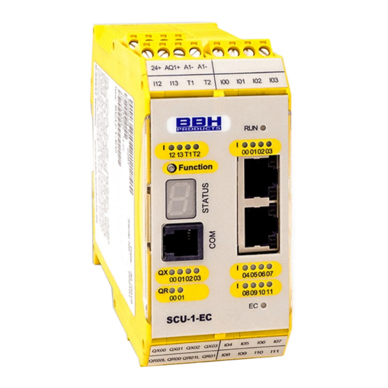
- Page 75 Programming manual SCU-series Furthrmore, the barriers only clear the way (via the Slave outputs)in the best-case scenario The data transfer between Master and Slaves is effected via FSoE. FSoE—network plan: FSoE-Master Master in switch cupboard hall 12: SCU-1-EC Monitoring of the end FSoE-Adr.: 0 position, with Start, FSoE-ID: 0...
-
Page 76: Selecting The Units / Network Components
EtherCAT. – The differenciation is made via parameters. Slaves the read-in of axle data: • SSB... (Safe Sensor Box – reading in of encoder data of 6 encoders BBH) • SDU… (Safe Drive Unit – reading in of encoder data of one encoder BBH) •... - Page 77 Slaves for IOs: • Beckoff EL … (IO unit by Beckoff) • SIO-… (Safe IO – input data and output data BBH) • (– reading in of external IO data einlesen LT-i) Figure 52: selection of Slaves NOTICE: These units are predefined and are available at the installation of the SafePLC .
-
Page 78: Fsoe Settings Of The Units / The Network Options
Programming manual SCU-series Figure 54: selection of units 4.4.4. FSoE settings of the units / the network options The FSoE-Master is automatically set to FSoE and has the preset address 0 (cannot be changed). 4.4.5. Optional Fieldbus interface With the SCU-x-EC/NM variants an additional Fieldbus interface can be configured. 1. - Page 79 Programming manual SCU-series 2. Afterwards, in the library window “Local network“ the symbol “Feldbus EtherCAT“ can be clicked on to change the settings in the „Properties“ window. In the “Properties” window, the additional “Network Type“ can be selected. Figure 56: EtherCAT Network 3.
- Page 80 Programming manual SCU-series The following properties apply to the units in our example: SIO1 SIO2 Comment Module address: as fixed in plan Cycle timet: 8 ms 8 ms as per Master Master cycle FSoE-Slave-addr. and -ID: as fixed n plan FSoE-Watchdog: 200 ms 200 ms...
-
Page 81: Determining The Inputs And The Outputs Of The Units
Programming manual SCU-series 4.4.6. Determining the inputs and the outputs of the units After the units are selected, their inputs and their outputs are determined in the SafePLC – tab “Wiring scheme”. Figure 58: Insert IO element By selecting it and dragging it into the main window, an input element or an output element from “Library”... - Page 82 Programming manual SCU-series For our example we had determined the inputs and the outputs. Now, the inputs and the outputs set: Master with Start button and Help button, Emergency-Stop button, Reset, 2 outputs Figure 60: IO-elemente inserted Master The assignment must be made separatel for each unit incl. all Slaves – here Slave1: •...
- Page 83 Programming manual SCU-series the other Slaves are assigned accordingly: • In our example: Slave2: 2 buttons (Start) + 4 x Emergency-Stopt + 2 switches (barrier + lamp) Slave3: 1 button (Start) + 2 x Emergency-Stop + 2 switches (relays to interrupt other functions) For units with an encoder connection, also these encoder connections must be given.
-
Page 84: Determining The Functions
Programming manual SCU-series 4.5. Determining the functions The elements inserted in the wiring plan are shown in the left library window which can also be used in the function chart. In the tab “Functional scheme“ the (safety) functions can be determined. These functions can be entered according to the SafePLC²... -
Page 85: Embedding Of Existing Slaves From External Companies
These Slave-units are included in the library and can be integrated according to the chapter “Selecting the units / network components” just like the units manufactured by BBH. Via drag & drop, the units are drawn from the “Library” in the window “Terminal Scheme”. - Page 86 Programming manual SCU-series 1. For the Slave-unit SDC a module address must be indicated. The module address must be taken from the FSoE-network plan. The number of axles can be specified in the field “Axles“. Afterwards, the Profiles of the different axes can be selected in the field “Profiles“...
- Page 87 Programming manual SCU-series 2. The encoder settings for the respective / selected axles must be set as follows: • By clicking on the desired axis symbol, the properties can be shown in the window “Properties”. Klick Figure 67 SDC axes •...
-
Page 88: El1904, El2904, Ax5805, Ax5806 (Beckhoff)
Programming manual SCU-series 4.6.2.2. EL1904, EL2904, AX5805, AX5806 (Beckhoff) After one or more Slave-units, type EL1904, EL2904, AX5805, AX5806 have been integrated, these Slave-units are shown in the Windows “Local Network” and “Terminal Scheme”. Figure 69: EL…. und AX…. In the terminal schemen In the wiring plan, one sheet per inserted unit is created. - Page 89 Programming manual SCU-series Figure 71: IO-Slave-units EL x904 with terninal assignment The properties of the respective units can be selceted in the window „ Properties “. Example of properties: modul address (according to network map), cycle time (longest period of all units in the network), unit address (according to network plan) , Slave address (according to network plan –...
- Page 90 Programming manual SCU-series The axis of the Slave unit AX580x can only be parameterised via “Properties”. It directly evaluates the information coming from the inverter The properties of the axis-Slave units are identical, and are more manageable because the connected axis is selected automatically: Figure 73: Properties of the axle-Slave-units AX 580x After the Slave units have been parametrised, they are available in the network.
-
Page 91: Embedding Not Pre-Defined Slaves
Programming manual SCU-series 4.6.3. Embedding not pre-defined Slaves ➔ This option will be available in the later versions of the manual. ➔ To embed not pre-defined Slaves, please contact the manufacturer 4.6.4. Adding input elements The input elements create the digital connection between one or more connected sensors or further subordinate switching devices in the system. -
Page 92: The Logic Modules
Programming manual SCU-series 4.6.6. The logic modules These modules are the basis for the creation of a program for the safety application. They enable the logical connection of the inputs with monitoring functions to the outputs. Only in the “Funktionsplan” [Function Chart] view, it is possible to insert logic modules. Otherwise, the corresponding module commands are disabled. - Page 93 Programming manual SCU-series The programme automatically creates a new connection in the terminal scheme and in the circuit diagram. The program draws the connection by inserting additional control points (break points) on the basis of a bisection algorithm. The graphical representation can be adjusted and the general representation can be optimised by moving the function blocks (if automatic arrangemetn has been deenabled).
-
Page 94: Using Groups
Programming manual SCU-series 4.6.8. Using groups Function groups connect several function blocks to a superordinate logical structure. This matching block group is created within the function group, and is connected via this block. Figure 75 function group By this grouping, the function block diagram obtains a clear structure. Via the Export function or the Import function, it allows the creation of an individual function library. - Page 95 Programming manual SCU-series Message window All results of the compilation are displayed in the message window. If errors are detected, the message window appears automatically. Tip: Use the “Quick Jump“ to jump directly to the respective block in the diagram by double clicking on the displayed block ID in the message window.
-
Page 96: Transferring The Program To The Device
Programming manual SCU-series 4.6.10. Transferring the program to the device This section describes the transfer of data and of the program to a safety module. If the interface has been started (via the device’s button ), the device’s interface toolbar appears. The toolbar contains connection tools and transmission tools. -
Page 97: Connection Settings
Programming manual SCU-series 4.6.10.1. Connection settings: Timeout Communication timeout can be set in milliseconds. RS-232 Cable The COM interface used by the Windows driver must be configured. Ethernet The IP address must be configured. PC sided separation After 8 s at the latest, the system detects that the connection no longer exists and cannot be restored automatically if the connection shall be re-established. -
Page 98: Diagnostics
Programming manual SCU-series 4.6.11. Diagnostics After the device interface has been enabled, the “Diagnostics” button is available. If you click on the „Diagnostics“ button, the diagnosis window appears. The diagnosis cannot be performed simultaneously with the range function. NOTICE: A correct diagnosis requires an adaption of data between function chart and equipment configuration. - Page 99 Programming manual SCU-series Encoder position: shows the position values for encoder A and encoder B, transmitted by the encoders. You can mark the current position with the “Snapshot” button. The program shows the distance parameters from the registered position. Encoder interface: displays the voltage difference of the output modules and the status of the input jumpers in the encoder interface.
-
Page 100: Diagnosis Process In The Function Block Diagram
Programming manual SCU-series 4.6.11.1. Diagnosis process in the function block diagram The most important prerequisite for diagnosis is to start the programme. The “Start” button in the symbol bar “Connection” is grey. 4.6.11.1.1. Diagnosis in the work surface The diagnosis in the work surface is only possible if the user has selected the tab „ Function blocks”... - Page 101 Programming manual SCU-series After the selection, click on the “block Diagnosis“ button . After a click on the button, the blocks are transferred int o the monitoring list. Figure 80 Selected blocks on the work surface The monitoring list shows the symbol address, the logic value and the description of every addedd block.
- Page 102 Programming manual SCU-series Information: The symbol addresses shown in the list are also used for compilation and itn the validation report. Tip: With the command “Select all” in the context menu (right mouse button) all files in the function plan can be selected. Now, the selected files can be diagnosed if the information in the function chart matches with the functions in the actively connected SCU system.
-
Page 103: Scope Onlinediagnostics
Programming manual SCU-series 4.6.12. Scope Onlinediagnostics Setting the drive monitoring requires an exact knowledge of the process data from the point of view of the SCU system. Knowledge of the chronological sequence of speed, acceleration and position is paramount. Only in this way, correct threshold values and restrictive parameters can be set. The range function is available in the dialogue window oft he device interface. - Page 104 Programming manual SCU-series The following selections are possible: • Encoder data • Speed sensor • Data of block SSX1 • Data of block SSX2 • Data of block SSX3 • Data of block SSX4 • SEL (time-based) • SLS filter •...
- Page 105 Programming manual SCU-series Collection / Stop: starts or stops the recording. Pause: Press the “Pause“ button to stop the displayed values in the main diagram. The data are still available in the cache. Reset: reset of diagram values and process data. Tip: With a double click in the main diagram window, the cursor is inserted at this position.
-
Page 106: Procedure Of A Measuring In The Range
Programming manual SCU-series 4.6.12.1. Procedure of a measuring in the range After the range window has been opened, it still stands on “Stop“, i.e., no cyclical process data from the SCU system are read. To carry out a measurement that is faultless to the greatest extent, you should proceed as described below. -
Page 107: Measurement Plans
Programming manual SCU-series 4.6.12.5. Measurement plans Encoder data • Functions Recirding of scaled position values of system A and system B over the whole period. • Recording of process data and acceleration over the period. Information: After the reciprocal comparison of the two channel values, the process value of the position is generated internally from the channel. - Page 108 Programming manual SCU-series • Output Speed A in [rpm] in red • Speed B in [rpm] in green • Speed differénce in [rpm] inyellow • Selectable SCU output in grey • Two cursor values – positionable Information: Optionally, the assigned colours can be adjusted. Data blocks SSX1 –...
- Page 109 Programming manual SCU-series Filters SLS filter Function • Monitoring of the maximum velocity or speed of a drive • Recording of process data for velocity via the position or via the period of time. • Visualisation of current position in the form of a parallel cursor. •...
-
Page 110: Configuration Report
Programming manual SCU-series 4.7. Configuration report SafePLC uses the validation function („Device interface →produce report”) to produce a configuration report for equipment configuration. This function is only available with an active connection to an SMX system. This function can also be enabled by selecting the field “Validierungsbericht erstellen“... - Page 111 Programming manual SCU-series The report is created as a PDF file. The report is saved in a file and can be edited afterwards. ATTENTION: The printed file serves as template for the safety-relevant check! NOTICE: The report can be stored only after the logic plan has been crated. The created file (*.pdf`) has the same name and is situated in the same list as the corresponding logic plan.
- Page 112 Programming manual SCU-series Step: fill in contact person Plant: Plant (phone) phone number Plant (fax): fax number Customer: operator of the equipment Customer (phone: phone number Customer (fax): fax number Suppliert: manufacturer of the device / the equipment Supplier (phone): phone number Supplier (fax n fax number...
- Page 113 Programming manual SCU-series Step: individual check of the system components This section contains control boxes that should be marked if the given information is correct. Visual check for personal injuries and correct fastening: Component documentation is available: Visual check for deviations from the installation guideline: Device type: Enter device type, e.
-
Page 114: User Management
Programming manual SCU-series 4.8. User management Via the user management, logic diagrams can be locked against unintentional or unauthorised changes. The access to function blocks in the current logic plan can be deenabled or enabled. This means, that in a disabled logic diagram all menu options and toolbars for adding function blocks are grey (= disnabled). -
Page 115: Device Interface
Programming manual SCU-series 4.9. Device interface The device interface is displayed in the device window. This window contains advanced communication options, e. g., programme transmission, diagnosis and range monitoring by connected SCU devices. If the device interface is opened, the programme automatically starts the compilation. - Page 116 Programming manual SCU-series Generate report: Creates a PDF file of the SCU configuration for the connected device. The text file lists the parameters of the configured modules and of the AWL programme. The print must be confirmed and approved by TÜV according to the relevant guidelines. Send network configuration: Transmits the set network parameters (not necessary for all modules).
-
Page 117: Export Window
Programming manual SCU-series 4) Programme status a. Idle – Programme has completed all tasks of the control b. Upload – Programme uploads into the SCU system c. Binary download – Program downloads the configuration from the deivicer d. Diagnostics – Program uses diagnostics instruments in the “Diagnostics” tab. e. - Page 118 Programming manual SCU-series NOTICE: The connection settings are described in chapter 4.6.10.1. After the connection has been established, and the “OK” button has been pressed, the main window with the control survaces for parameter export appears. Figure 90 The following menus are available: File, Edit, View, Connection and Validation. Commands in the “Datei”...
- Page 119 Programming manual SCU-series Figure 92 „Export option“ window Exit– Close the parameter export window. Commands in the “Edit” menu: The commands in this menu are intended for work in the “Parameters” tab. Figure 93 HB-37500-820-10-12F-EN SCU Programming manual Page 119 of 252 Status: 19.03.2021...
- Page 120 Programming manual SCU-series Figure 94 parameter export, menu "edit" Undo Selected – Resets the selected value to the default value. Undo Global – Resets all parameter changes to the default values. Figure 95 User confirmation before resetting parameter values Change value – Change of the selected value. Value change is also achieved by double clicking on the value with the left mouse button.
- Page 121 Programming manual SCU-series Deactivate Global– Disables all parameters (series) for all parameters used. Lock Values – Locks the selected value. A dialogue window appears to enter a password. The blocked values are blocked for use in other programmes. Figure 96 After locking the values, the "Enter password" dialog box appears. Unblock Values –...
- Page 122 Programming manual SCU-series Always in the foreground – display of export window always in the foreground. Commands in the “Connection” menu: The surface of this menu depends on whether the SCU is connected or not. Figure 99 Surface, of disconnected SCU. Figure 100 Surface if SCU is connected and runs.
- Page 123 Programming manual SCU-series Commands in the “Validation” menu: Figure 101 parameter export, menu "Validation" Genrate export – This function connects two commands: “Create Export” and “Create Export Report“. Validate and save – validating and saving of parameters. Generate report – creates a PDF file or an Excel file of the current SCU configuration for the connected device.
- Page 124 Programming manual SCU-series Symbols for parameter export: Figure 103 symbols in the device interface – not connected Figure 104 symbols connected Connect: starts the connection with the SCU system. Disconnect: disconnects an active connection. Execute: starts the program sequence in the “Connected” mode“. Stop: Stops the program sequence in the “Connected”...
- Page 125 Programming manual SCU-series “Control” tab Figure 105 "control" tab Send PRF chart (Position Reference Function): transmits all files necessary for using the PRF function, e. g. the position chart. For further information about the PRF function, c.f. chapters 10.3.3.7 and “TD-37350-820-11-xxF PRF description of the application Send SMF matrix (Safe Matrix Function): transmits position data of the coordinate matrix.
- Page 126 Programming manual SCU-series The “Project” tab In this tab, it is possible to fill in text boxes and to export this information with the exported parameters. These boxes can also be blocked. Blocked boxes cannot be edited after having been exported to and opened in another program.
-
Page 127: Networks
Programming manual SCU-series 4.11. Networks 4.11.1. Master to Master (SMMC) 4.11.1.1. Description Global network with an SMMC Safe-Master-Master-Communication. The minimum are 2 Masters; the maximum are 4 Masters. 4.11.1.2. Creation The user must connect a Master that supports SMMC. If the user connects a second Master that supports SMMC, the following window appears: Figure 107 Select "Enable Global Network"... - Page 128 Programming manual SCU-series Figure 108 View "global network", SMMC HB-37500-820-10-12F-EN SCU Programming manual Page 128 of 252 Status: 19.03.2021...
-
Page 129: Configuration
Programming manual SCU-series 4.11.1.3. Configuration Joint configuration If the user clicks on the SMMC line in the global network Figure 109 "global network", SMMC-line or if he selects SMMC in the browser, Figure 110 The SMMC properties in the properties window. The SMMC properties appear in the properties window. - Page 130 Programming manual SCU-series Figure 111 Properties window, master property SMMC cycle time Cycle time of the SMMC communication in [ms] [16ms…4096ms] SMMC Timeout Timeout time of the SMMC communikation in [ms] [32ms…8192ms] Name Free input possible for users Individual Master configuration After a click on every Master device in the SMMC network, the properties with which these devices can be configured individually appear in the properties window.
-
Page 131: Use
Programming manual SCU-series Figure 113 4.11.1.4. Use Every device can write 16 bit as output on SMMC. By the connection with SMMC, these bits are defined as “Terminal off”. SMMC Terminal Out “Output connection “ Every device can write 16 bit as output on SMMC. By the connection to SMMC; these bits are defined as “SMMC Terminal Out”... - Page 132 Programming manual SCU-series SMMC “Terminal In“ [SMMC input connection] Every device can read bits from other devices, and it can read its own bits Figure 115 SMMC Terminal In A restricted number of configurable common bits for every device and this Master can be assigned to logic as SMMC “Terminal Out”, and can later on be used in the functional layouts of other Masters in these Masters‘...
-
Page 133: Fieldbus
Programming manual SCU-series 4.11.2. Fieldbus 4.11.2.1. Description Fieldbus is the name of a group of industrial computer network protocols for real-time transmission control. Fieldbus is standardised in theIEC 61158 standard. Fieldbus network protocol: Non-safe networks • PROFINET (currently only safe data) •... -
Page 134: Configuration
Programming manual SCU-series This view shows a connection of the device with the superordinate SPC. In the local network, the fieldbus is activated separately for each device. The use of the fieldbus can be safe, non-safe or both. The use can be selected in the properities window. - Page 135 Programming manual SCU-series Network use – possible selections: safe, non-safe and both Figure 118 activated non-safe use Non-safe use For non-safe use, currently onlyTCP/IP is available, that can be used as communication interface for SafePLC Diagnostics data are only transmitted via the EtherCAT connection (FSoE Master). The data can be parametrised via the functional outputs.
- Page 136 Programming manual SCU-series In one block also more than one functional output can be configured. The illustration shows a functional output with 3 outputs. Figure 122 functional output with 3 outputs Properties window of a functional output Figure 123 Properties window of a functional output HB-37500-820-10-12F-EN SCU Programming manual Page 136 of 252 Status: 19.03.2021...
- Page 137 Programming manual SCU-series Safe use Currently, PROFIsafe Slave and FSoE Slave can be selected for safe use. Figure 124 Selection of secure network connections The following settings are possible: • Logical data input – settings range from 8 bit to 96 bit. •...
- Page 138 Programming manual SCU-series Figure 126 F-Bus Output: function block and properties window Process data outputs for the SCU Currently, only the status can be transmitted as a process data word. Figure 127 properties window "Fieldbus EtherCAT" Reset via network If safe communication is used, a device set (alarm messsages) can be configured via safe communication.
-
Page 139: Fastchannel
Programming manual SCU-series 4.12. Fastchannel 4.12.1.1. Description In the SCU FSoE I/O, Slave goups with a maximum process data width of 16 bit can be operated in the Fastchannel mode. The processing time of a Fastchannel connection is indicated in the installation manual 4.12.1.2. -
Page 140: Device Configuration
Programming manual SCU-series 4.12.1.3. Device configuration The Slave units used in the Fastchannel must be configured. To configure the Slave units, “FC Connection” must be activated. Figure 130 FastChannel function plan, FC-connection activated in slave unit properties window NOTICE: • Slave units that are configured with Fastchannel can only be used in the Fastchannel fucntion chart. -
Page 141: User Program
Programming manual SCU-series 4.12.1.4. User program The processing in the Fastchannel function chart is similar to the “Standard” function chart. There are restrictions with respect to programme size and with respect to the library. Logical program concatenation between “Standard function chart” and the Fastchannel function chart takes place via the function blocks FastChannel Flag Input and FastChannel Flag Output. - Page 142 Programming manual SCU-series FastChannel Output FSoE Slave output bit Figure 132 Access ID: selection of Slave number and bit number FastChannel Input Reading of FSoE Slave input bit Figure 133 Access ID: selection of Slave number and bit number merker FastChannel Merker Output Flagbit for use in the “Standard”...
- Page 143 Programming manual SCU-series FastChannel Merker Input Reading of flag bit from “Standard” function chart to FastChannel function chart Figure 135 Access ID: selection of bit number of flag Programne example: Enabling of output on Slave device via “Standard“ function chart (standard reactiontime) and disabling via FastChannel processing (FastChannel response time) HB-37500-820-10-12F-EN SCU Programming manual Page 143 of 252...
-
Page 144: Content Of The Library
Programming manual SCU-series 4.13. Content of the library The library offers all available blocks to create the desired function block diagrams. Only the elements that can be used in the selected plan are displayed. The blocks can be added in the plan view, and they can be edited in the properties window. Figure 136 View of the library –... -
Page 145: Device Modules
Programming manual SCU-series If no resources (memory) for the monitoring program are available in hte SCU module, the components of the function blocks are no longer shown in the library view. This is the case if, e. g., all digital connections of an SCU module are occupied, or if all timer modules have been used. -
Page 146: Input Elements
Programming manual SCU-series 4.13.2. Input elements Figure 138 List of input units Input elements create the digitial connection between one or more connected sensors or other subordinate switching devices in the SCU system. They provide data about the operating status of the plant that is monitored by the SCU module. - Page 147 Programming manual SCU-series Information: The configuration of the input block has significant effects on the performance level. (cf. Installation manual). Inputs that are not used are always assigned to Impulse 1 (standard configuration). Nevertheless, in the configuration report inputs that are not used, are listed with the standard configuration.
- Page 148 Programming manual SCU-series • Monitoring Release of the monitored input element with a falling edge of the corresponding monitoring input. This is always necessary if the monitored input element is to b e switched. Example: start of a drive only after confirmation by the operating personnel. With a monitored startup type, an additional connector is provided to connect the startup element.
-
Page 149: List Of Input Elements
Programming manual SCU-series 4.13.2.1. List of input elements The “Confirm” button Switch type Description Comment 1 (1 N.C.) 1 opening contact Activation switch (standard) 2 (1 N.O.) 1 closing contact Activation switch (standard) Activation switch with larger number of 3 (2 N.C.) 2 opening contacts requests 4 (2 time-monitoredd N.C.’s) - Page 150 Programming manual SCU-series Two-hand control Switch type Description Comment Two-hand switch with higher requirements; 11 (2 toggles) 2 closing contacts + 2 opening contacts typ III C 12 (2 N.O.) 2 closing contacts Two-hand switch (monitored)); type III A Information: These input elements cause a fixed impulse assignment which the user cannot influence.
- Page 151 Programming manual SCU-series Operation mode switch Switch type Description Comment 13 (N.C. N.O.) Selection witch opening contact / closing contact Selection switch (monitored) 14 (3 Phasen) Selection switch 3 steps Seklection switch (monitored) 15 (4 Phasen) Information If the status of the switch is changed, the SafePLC² programme warrants that the outputs of the module are disabled.
- Page 152 Programming manual SCU-series Start element / reset element This input element offers an extended monitoring function and the possibility to reset an alarm that has occurred. Figure 140 Properties of the start element / the reset element Use of the monitored states With the start monitoring being enabled, automatically a special AWL code segment for the monitoring of an assigned input segment during a restart or during the reset of an alarm of the equipment to be monitored/ the alarm tob e monitored is created.
- Page 153 Programming manual SCU-series Startup type Function Plan Auto Automatic start after the recet of the Start equipment Geräte-Anlauf equipment or after the input has been enabled. Switching function Schaltfunktion The output of the input element changes to “1”when the safety Ausgang Output circuit is closed / active according to...
-
Page 154: Listing Of The Startup Types Via The "Enable" Button
Programming manual SCU-series 4.13.2.2. Listing of the startup types via the “Enable” button The input of the start element to be monitored must be connected with the output of the input element by the description “Start element”. Various elements can be monitored. Figure 141 Start block / reset block connected with monitored start Information: When the corresponding input element is edited, the connection to the start element is deleted, and cannot be restored any more. - Page 155 Programming manual SCU-series In case of error messages of the type “Fatal Error “, the SCU module must be restarted. The input of the alarm reset can be operated with 24 V continuous voltage and is triggered by the edge. •...
-
Page 156: Output Blocks
Programming manual SCU-series 4.13.3. Output blocks Figure 143 List of output elements The output blocks create the digital connection between one or several external switching circuits in the SCU system. Every block is triggered by a logic input signal “0” or “1” via the function chart. EMU monitoring With this device variant, EMU cannot be used. -
Page 157: List Of Output Elements
Programming manual SCU-series 4.13.3.1. List of output elements HiLo semiconductor Figure 144 Properties window "HiLo semiconductor" Output type Standard: “HISIDE“(= P-circuit) or “LOSIDE“ (= M-connection) can be selected as standard outputs. The use of simple standard outputs is not suitable for safety outputs. Redundant: This option obliges a combination “HISIDE”... - Page 158 Programming manual SCU-series Highside semiconductor Figure 145 Properties window "Highside semiconductor" HB-37500-820-10-12F-EN SCU Programming manual Page 158 of 252 Status: 19.03.2021...
- Page 159 Programming manual SCU-series Relay Figure 146 Properties window "Relay" Output type Standard: 2 simple relays (K1 to K2) can be evaluated independently. Redundant: Two relay outputs are combined, and are always interconnected. NOTICE: Observe the explanatíons in the installation manual when inserting a relay in safety applications. For EMU monitoring, c.
- Page 160 Programming manual SCU-series Semiconductor Figure 147 Output as auxiliary outputs Certain semiconductor outputs can only be used as auxiliary outputs. Thus, they are not suitable for safety applications. (For details, see the installlation manual.) HB-37500-820-10-12F-EN SCU Programming manual Page 160 of 252 Status: 19.03.2021...
-
Page 161: Encoder Combinations
Programming manual SCU-series 4.13.4. Encoder combinations Encoder configurations are configured in the Slave blocks. Via FSoE, they are transferred to the SCU modules as safe position ans safe velocity. 4.13.4.1. Setting the encoder‘s range The setting of the two encoders for the detection of position and velocity can be set in “Eigenschaften”... -
Page 162: Setting The Axle
Programming manual SCU-series 4.13.4.2. Setting the axle To use the encoder for monitoring functions, the axisisust be confgured. The settings depend on the encoder type used: HB-37500-820-10-12F-EN SCU Programming manual Page 162 of 252 Status: 19.03.2021... - Page 163 Programming manual SCU-series Parameter Description Value Encoder type Display encoder type No input possible Process encoder Not supported. Info only. Axle type Axle range Finite modules Scaling type Linear or rotatory setting Linear Rotatoriy Rotatory Unit Linear-> mm/s Linear-> m/s Rotatory ->...
-
Page 164: Function Block
Programming manual SCU-series 4.13.5. Function block 4.13.5.1. Logic function Figure 148 Listing of the logic functions in the library These blocks are the basis for the creation of a programme for the safety application. They allow the logic connection of the inputs with monitoring fuctions with the outputs. The insert of function blocks is only possible in the “Funktionsplan”... - Page 165 Programming manual SCU-series AND block “AND“ links of not more than 5 output signals of other function ks. The AND-link provides the signal state “1“for all input signals “1“as logic result. Otherwise, it is “0“. Figure 149 properties window "AND" block NOTICE: The number of input connections can only be reduced in case of free connections.
- Page 166 Programming manual SCU-series FLIP FLOP-Block Setting / reset of a contact element. The switch element has the following properties: • The logical result during the initialization of element is “0”. • The logical result changes to “1” if an edge change from “0” to “1” occurs in the “Setting” input.
- Page 167 Programming manual SCU-series cFLIP FLOP block Set / reset switching element. This switching element saves the state in a tension-proof way. After a POR, the state saved last is restored. Functioning like RS FlipFlop. If both inputs are set to “1”, the result is “0”! Figure 152 properties window “cFLIP FLOP”...
- Page 168 Programming manual SCU-series Configurable Boolean This module always provides the value “1”. This function can be used for programming static states in the function block. Figure 154 properties window of configurable boolean NOT block The logical result of this function block is the negation of the input signal. Here, the term “negation”...
- Page 169 Programming manual SCU-series OR-Block “OR“connections of not more than 5 output signals from other function blocks. The OR connection provides the signal state “1“ for at least one input with the signal state “1”. Otherwise, the signal state is “0”. Figure 156 properties window of OR function block HB-37500-820-10-12F-EN SCU Programming manual Page 169 of 252...
- Page 170 Programming manual SCU-series Timer Function block that starts a meter in case of an edge change. After the fixed time lag, the result is “1” or “0”. Figure 157 properties window „Timer“ Block-ID: Timer number. The timer number can be set when the timer is plugged in. If all timers are used, the timer command in the menu is disabled.
- Page 171 Programming manual SCU-series Behaviour Activation of Function Time diagram timer Fall-delayed Falling edge Delayed Rising edge closing Impulse Rising edge Periodical Rising edge Save According to Voltage-proof saving of timer value. After unit POR, the timer permanent function value saved last is loaded again. After loading of configuration data on the SCP unit, the saved timer value reset again (“0”)..
- Page 172 Programming manual SCU-series Edge detection Block for edge detection rising, falling or both. Figure 158 properties window of edge detection Edge detection: • Positive: Evaluation of rising edge. Signal at block output changes to “high“, if rising edge is detected at block input.
- Page 173 Programming manual SCU-series Restart-block Block for confirmation signal for stopping and for the following request to restart the application. The basic requests for the block are: • Commissioning of the device (cold start after the Power-Cycle) • Restart of the device (warm start after programme download, software reset etc.) Type of reset start “Monitored”: “Release”...
- Page 174 Programming manual SCU-series Release: The output switches to “high”, if the following conditions are fulfilled+# Dummy-block The signal channel enables the functional transmission of data from the process image to a connectec fieldbus. The signal channel consists of two parts: The first part consist of logic data with 56 bit.
-
Page 175: Safety Functions
Programming manual SCU-series 4.13.5.2. Safety functions The safety functions are an important function of of the SCU system. The safety functions are preset functions for. Preset functions are available for: • Speed monitoring • Position detection • Monitoring of limits and target positions •... -
Page 176: Overview Of Safety Modules
Programming manual SCU-series The function to monitor position, speed and shut-off is enabled only after the successful configuration of an encoder. After the encoder has been successfully configured, the respective functions can be inserted, if the SCU-module has resources available for this purpose. After all resources have been used, the menu option for the corresponding function block is deactivated. - Page 177 Programming manual SCU-series FDB (FSoE Disconnect Block) Safe disconnection of an FSoE connection Number: c. f. “Overview of safety modules“ Function: “Disconnect Block“ is used to temporarily disable the FSoE connection- The detection, which device must be disabled, is set via the FSoE address. By the function, an error status in the Master in case of defined shut-off / defined disconnection of a Slave block is avoided.
- Page 178 Programming manual SCU-series FSoE adress FSoE Slave adress to shut down the FSoE connection of the Slave blockon which the function shall act. Timeout Timeout in ms, until FSoE connection is actively expected after deativation of the Disconnect block. Signal Description Enable 0: FSoE connection is not interrupted...
- Page 179 Programming manual SCU-series EDM (External Device Monitoring) monitoring of external switch contacts Number: c. f. “Overview of safety modules” Function: Normally, additional switch devices are necessary for contact multiplication and for power multiplication. These switching devices are triggered via the outputs of the safety block.
- Page 180 Programming manual SCU-series Response time Variables time window (turn-on delay) for the test of the external switch contact Min{T 16 msec Max{T = 3000 msec Release time Variable time window (turn-off delay) for test of the switch contactss Min{T 16 msec Max{T = 3000 msec Reset...
- Page 181 Programming manual SCU-series SEL (Safe Emergency Location) Monitoring of the maximum movement range Amount: c. f. the chapter “Safety functions” Function: monitoring of the permissible speed in relation to the relative distance to the maximum limit of the movement or to the maximum limit of the adjustment range.
- Page 182 Programming manual SCU-series Trapezförmiges Geschwindigkeitsprofil: X1 = Min. Position X2 = Max. Position V0 = maximum sped for ( X1 + BX ) < X < ( X2 – BX ) F = type of the speed profile (trapezoidal or sigmoid) -Trapezoidal BX = brakes/procimity range -Sigmoidal...
- Page 183 Programming manual SCU-series Output function: Range X < X X > X2 X >= X1 X <= (X1 + BX) V < limit curve X >= (X2 – BX) X <= X2 V < limit curve X >= X1 X <= (X1 + BX) V >= limit curve X >= (X2 –...
- Page 184 Programming manual SCU-series Activate permanently If this option is set, the monitoring function has no input connection. This function is active from the start of the device. Curve type - Linear Linear calculation method for the stop distance in relation to limit position Curve type = linear [Kurvenart = linear] - Sinoidal...
- Page 185 Programming manual SCU-series Input example 1: At a production machine, access to the work zone shall be guaranteed at certain positions of the main input axis for manual input or for settings. In this position, the drive remains active, and is only monitored for a standstill.
- Page 186 Programming manual SCU-series SLP (Safely Limited Position) Target position monitoring Amount: cf. The chapter “Safety functions” Input: standardised position signal X from encoder interface RESET function: The violation of the permitted monitoring range and requires a RESET confirmation. The RESET confirmation is alternatively carried out via: ▪...
- Page 187 Programming manual SCU-series Figure 160 properties window of SLP monitoring Parameters: Curve type -Linear Linear calculating method for the stop distance in relation to the target position = brake ration / proximity range X2-X0 = measured length, cf. encoder configuration = target position = cw input enabled (pos + stop_distance...
- Page 188 Programming manual SCU-series -Sigmoidal Quadratic calculation method for the stop distance in relation to the target position Curve type = Sigmoidal [Curve type = quadratic] Max. acceleration Max. acceleration value within BX Max. acceleration change Value of maximum permissible acceleration change in BX when using the quadratic calculation method.
- Page 189 Programming manual SCU-series Time characteristics of the “SET/QUIT“ process: QUIT SOS_Enable Assumption position Save position Processing cycles The sequence is time-monitored and triggers an ALARM if the expected values are exceeded. ATTENTION: The maximum time frame is 3 seconds! Position tolerance Tolerance value for the TeachIn position.
- Page 190 Programming manual SCU-series SCA (Safe Cam) Monitoring of the position range by speed monitoring / velocity monitoring Amount: cf. “Overview of safety modules” Function: monitoring of a parametrisable position range with assigned minimum limit and maximum limit. In the permitted range additionally monitoring of the speed.
- Page 191 Programming manual SCU-series Output function Range X < X1 OR X > X2 X >= X1 X <= X2 V < V0 X >= X1 X <= X2 V >= V0 Ranges can be defined as overlapping and as nested. HB-37500-820-10-12F-EN SCU Programming manual Page 191 of 252 Status: 19.03.2021...
- Page 192 Programming manual SCU-series Figure 161 properties window of SCA monitoring Parameters: Permanent activationn If this option is set, the monitoring function has an input connection. The function is active from the start of the device. Lower limit position X1 Lower limit position Upper limit position X2 Upper limit position Speed threshold...
- Page 193 Programming manual SCU-series Direction-independent release Currently not supported Negative encoder counting direction: Currently not supportedt Positive encoder counting direction: Currently not supported Activation and release of the speed direction Currently not supported Travel monitoring Currently not supported Example of input: At a production machine the access to the work zone for manual insert or rather, manual setting shall be released for certain positions of the main input axis.
- Page 194 Programming manual SCU-series RESET function: Violation of the permitted monitoring range is saved and requires a RESET confirmation. The RESET confirmation is alternatively carried out via: ▪ RESET function in the group of the Input elements. Function button at the front side of a basis group ▪...
- Page 195 Programming manual SCU-series - Signoidal speed profile (S-shape) The sinoidal speed profile shows the change of speed over the time, or rather, the course of speed over the time. Max. acceleration AM Value of maximum acceleration within BX S-smoothing time VZ The smoothing time VZ means the period in which speed does not change linearily, or rather, the period for acceleration change from a=0 or a=amax or vice versa.
- Page 196 Programming manual SCU-series Output function Range T < T Latency T > T Latency V < V Limit curve T > T Latency V > V Limit curve Every function block can be parametrised to stop-category 1 or stop-category 2. In STOP-category 2, after the expected standstill the SOS function is activated automatically.
- Page 197 Programming manual SCU-series Curve type - liear curve typ Linear speed and constand acceleration curve for the stop sequence -Sinoidal curve type Sinoidal speed an linear acceleration curve for the stop sequence Latency time standard Latency time until the ocurrence of the delay Max.
- Page 198 Programming manual SCU-series Tolerance value of current speed. If the current speed is greater than the current limit curve + tolerance value, energy supply is disconnected. Max. acceleration Determines the increase of the stop curve. S- slip time The slip time indicates the period, in which the curve’s form is sinoidal. The period before and after the acceleration a Reset Select Reset.
- Page 199 Programming manual SCU-series SLI (Safely Limited Increment) Monitoring of the maximum increment Amount: cf. “Overview of the safety modules Function: monitoring of the maximum increment Input: standardised position signal / speed signal V and X from encoder interface. Direction LEFT / RIGHT. RESET function Violation of the permitted monitoring range is saved and requires a RESET confirmation.
- Page 200 Programming manual SCU-series Range V < 0 DIRECTION FLAG = LEFT Relative travel distance < max. increment V >= 0 DIRECTION FLAG = RIGHT Relative travel distance < max. increment V < 0 (DIRECTION FLAG = RIGHTS Relative travel distance > max. increment V >...
- Page 201 Programming manual SCU-series Example of an activation: [Achse]: 1 Example of an input: The max. travel distance of the material feeding system of a production plant shall be safely monitored in jog operation. According to the risk analysis this travel distance is no more than 50 mm.
- Page 202 Programming manual SCU-series SDI (Safe Direction of Increment) Recognition of the direction Amount: cf. “Overview of the safety modules” Function: monitoring of the given rotational direction / the given motion direction Input: standardised position signal / speed signal X from encoder inferface. Direction flag LEFT / RIGHT.
- Page 203 Programming manual SCU-series Figure 164 properties window of SDI function Parameters: Speed monitoring mode Maximum tolerance threshold for speed in opposite direction Position monitoring mode Maximum tolerance threshold for position in opposite direction Reset Select Reset. Example of an activation: [axis]: 1 HB-37500-820-10-12F-EN SCU Programming manual Page 203 of 252...
- Page 204 Programming manual SCU-series Example of input: At a production device the speed of certain manual processes must be monitored for a safey-reduced value, and for the standstill direction and the movement direction must be monitored. The movement that shall be actively monitored is a rotating movement. The drive functions wih an elecric motor wih and integrated motor feedback system and an intermediate transmission.
- Page 205 Programming manual SCU-series SLS (Safely Limited Speed Control) Monitoring of a minimum speed Amount: cf. “Overview of the safety modules“ Function: monitoring of a minmum speed Eingang: standardised position signal X from the encoder interface RESET-function: Violation of the permitted monitoring range is saved and requires a RESET confirmation.
- Page 206 Programming manual SCU-series Figure 165 properties window of SLS function Activate permanently: Activate permanently The monitoring function is always active and does not have an input connector. Speed tolerance To activate speed monitoring Travel monitoring Currently not supported. Error distance monitoring Currently not supported.
- Page 207 Programming manual SCU-series SOS (safe standstill) Standstill monitoring Amount: c. f. “Overview of safety modules “ Function: standstill monitoring Input: standardized position signal / standardized speed signal RESET-Funktion: Violation of the permitted monitoring range is saved and requires a RESET confirmation.
- Page 208 Programming manual SCU-series X >= (X0 + DX ) Figure 166 properties window of SOS function Monitoring mode Determination of the monitoring mode for standstill upto a minimum speed threshold or up to a position range Maximum speed tolerance / maximum position tolerance Minimum speed or a permitted relative deviation from the current position at the time when the SOS function was enabled.
- Page 209 Programming manual SCU-series Input example 1: In a production device, at certain manual processes speed shall be monitored for a safeIy reduced value. Additionally, standstill and travel direction shall be monitored. The active movement tob e monitored is a rotating movement. The drive is an electronic motor with integrated motor feedback systeme and an intermediate gear.
- Page 210 Programming manual SCU-series MPM (safe synchronsation monitoring) synchronisation monitoring Amount: c. f. the chapter “Safety functions” Access-ID: identification of the function element Axis assignment: 1 Master axis 2-12 Slave axes Function: synchronisation monitoring Input: Standardises position siganals form the encoder interface RSET- function: Violation of the permitted monitoring range is stored, and a confirmation is necessary.
- Page 211 Programming manual SCU-series Figure 167 properties window of Multiaxes position monitoring Position of the Master Selection (mode) between Axis and Functional. Currently onlyone axis is supported. The supported axis is the referential axis for the comparison with the other axes. Number of axes Number of comparative axes 1…12 Permanent...
- Page 212 Programming manual SCU-series Reset Selection of Reset Axis x: • Numerator Numerator for the nomination of the position to the Master axis • Denominator Denominator for standardization position to Master axis • Ratio Display of nominator / denominator • Offset Only with Type->...
-
Page 213: Muting Functions
Programming manual SCU-series 4.13.5.3. Muting functions ECS (Encoder Control Supervisior) User-defined evaluation of the encoder status. Amount: cf. “Overview of safety modules” Function: Muting of encoder error RESET function: Violation of the permitted monitoring range is stored and requires a RESET confirmation. - Page 214 Programming manual SCU-series ICS (Input Element Muting) Muting of the monitoring of the digital inputs Amount: cf. the chapter “Safety functions” Function: Muting of the monitoring device of the digital inputs for correct impulses an correct input function according to the configuration Reset function: not applicable NOTICE:...
- Page 215 Programming manual SCU-series DEM (Dynamic Encoder Errors Muting) Amount: cf. the chapter “Safety functions” Function: muting of the alarm of encoder diagnostics functions from an adjustable limit speed. RESET function: no reset necessary NOTICE: The DEM function can only be used for axes that have been set without position processing.
- Page 216 Programming manual SCU-series Example: DEM-function axis1 with SLS according to Pld and SOS accrding to Ple. The enabling of DEM takes place when the door is closed. The closed status is controlled with a block for the door control. • Highest PI level = Ple, input must be Ple •...
- Page 217 Programming manual SCU-series irrelevant irrelevant irrelevant true true Encoder monitoring = true untrue Irrelevant irrelevant untrue true (no alarm occurred) true irrelevant irrelevant untrue untrue true irrelevant irrelevant untrue untrue Encoder monitoring = untrue true untrue untrue untrue untrue (an alarm untrue true true...
- Page 218 Programming manual SCU-series Figure 171 properties window of DEM function Parameters: Permanently activated: If this field is selected, the function i permanently enabled. The input connector of the block is deleted. Limit speed: When the speed value that is given in this case is exceeded, the muting function is enabled. If the activation is permanently disabled, additionally the status of the function block input is linked.
- Page 219 Programming manual SCU-series EOS (External Offset Setup) Setting of the encoder positions to the configured position value Amount: cf. the chapter “Safety functions” Access-ID: identrification of the function element Function: Calculation of a shift value for position encoders for a position encoder on the basis of a settable setting postion on the basis of the current encoder position.
- Page 220 Programming manual SCU-series Figure 172 properties window of EOS function Encoder -ID: selection of the sensor that is connected eto encoder A (= 1) or to encoder B (= 2). Encoder type: selection of encoder type. Preset value: preset value (set position) for the selected encoder. NOTICE: At the most one EOS function can be used for the absolut encoder value.
-
Page 221: Elements Of The Global Network
Programming manual SCU-series 4.13.5.4. Elements of the global network The global network elements include an SMMC output block and the corresponding input elements. Figure 173 Library window "Global network" SMMC “Terminal Out“[Connection point output] This block is an output of the SMMC. Every device can write 16 bits as output on SMMC. By the connction to SMMC, these bits are defined as “Terminal out”. -
Page 222: Elements Of The Fieldbus Network
Programming manual SCU-series SMMC “Terminal In“ [input connection point] This block maps the input of the SMMC. It is freely available after the user has configured the corresponding “Terminal out” [connection off] in a random function chart. Figure 175 Terminal In block of SMMC Number of bits: number of available bits for the input. -
Page 223: Connections
Programming manual SCU-series 4.13.5.6. Connections These elements are intended to prove a clear representation of the function charts. These elements provide “Input connection points / Output connection points”. Afterwards, the connections between the elements are drawn. Terminal In [input connection point] These elements provide connections for outputs. -
Page 224: Groups
Programming manual SCU-series Terminal Out [output connection point] This element facilitates the continuation of a signal that leads to an “Terminal In” [Set connection point] block. Thus, these elements can ony be inserted after a set connction point has been defined. Figure 178 Properties window of Terminal out Connecting direction: selection of the direction of the connection point on the desktop. -
Page 225: Creating A Group
Programming manual SCU-series 4.13.5.7.1. Creating a group: Creating a group module Creating a unique function group The library window contains an element for a new group. To add a new group, draw the symbol “New group“ from the library, and insert it in the work surface of the function chart. The created group does not have an input-output interface. - Page 226 Programming manual SCU-series If modules that have already been connected shall be added to a group by shifting, you should proceed as follows: 1. Shift the group block over the function block. The affected connections must all be situated in the group file.
-
Page 227: Setting The Group Administration
Programming manual SCU-series 4.13.5.7.2. Setting the group administration When you click on the group with the right mouse button, the context menu for lock management appears. With this function, the block administration of the frame is deactivated, and the blocks are connected to the group: •... -
Page 228: Export / Import Of A Function Group
Programming manual SCU-series 4.13.5.7.3. Export / Import of a function group A right mouse click on the group shows the export to the library. The modules of can be exported to the library. An exported group can be imported into a different group sheet. This export allows you to create a library. - Page 229 Programming manual SCU-series With this setting, the connection properties of the block can be determined as group input. • Group input This element shows the connection of the function blocks outside the group to external group elements. If possible, the block shall be situated on the left side of the group area. The output connection must be forwarded within the group.
-
Page 230: Commissioning
Programming manual SCU-series 5. Commissioning 5.1. Start-up sequence In case of a correct run, after every reset the following phases are completed. These phases are displayed on the front-mounted seven-segment display 7 Segment Mode Description Anzeige [segment display] Synchronization between the two processor systems, „1“... -
Page 231: Led Display
Programming manual SCU-series 5.3. LED display The SCU assembly has 2 LEDs: EC ST and RUN: Colour Displaye Meaning EC ST Init Green Blinking PRE-OPERATIONAL Green Single Flash SAFE-OPERATIONAL Green OPERATIONAL No errorr Invalid configuration Blinking Ocal error Single Flash Watchdog Timeout Double Flash No power supply voltage... -
Page 232: Validation
Programming manual SCU-series 5.6. Validation To guarantee the functioning of the implemented safety function, the user must test the parameters and the links. After commissioning and parametrisation have been completed, the user must test these functions. This test must be documented. Documenting is supported by the validation assistant (c. - Page 233 Programming manual SCU-series On the first page, general information must be filled in. Figure 181 Example: page 1 configuration report Afterwards, the configured values and the user programme must be validated. HB-37500-820-10-12F-EN SCU Programming manual Page 233 of 252 Status: 19.03.2021...
-
Page 234: Validating The Configuration
Programming manual SCU-series 5.6.2. Validating the configuration All set parameters must be checked and confirmed. Example: SCA configuration data HB-37500-820-10-12F-EN SCU Programming manual Page 234 of 252 Status: 19.03.2021... -
Page 235: Validation Of The Plc Programme
Programming manual SCU-series 5.6.3. Validation of the PLC programme 5.6.3.1. General information The IL programme is structured in the following way: Index: sequential n = line in AWL programme Command: for all permitted commands, c. f. the list “PLC commands“ Operand: for the processing code cf. -
Page 236: Input Elements
Programming manual SCU-series 5.6.4. Input elements The input elements are marked in the AWL code. SQH marks the start of an input element and SQC marks the end of an input element. SQH marks the number of the input element SQC marks the backup value of the input element logic. - Page 237 Programming manual SCU-series 5.6.5. Monitoring functions For the monitoring functions, there are two way of processing that generate additional IL code. 5.6.5.1. Cascading The following functions are cascadable: • SEL, SLS, SOS: The following code is generated: Example: SOS: MX.x DriveSOS_EN0.0.0 MX.y DriveSOS0.0.0...
- Page 238 Programming manual SCU-series 5.6.5.2. Axis groups Monitoring functions can be combined using axis groups. Basically, one monitoring block is one monitoring block is provided for every axis in an axis group. In the IL code, the individual results are summarized (AND).. •...
- Page 239 Programming manual SCU-series NOTICE: special function SRX: Result: axis group is differently linked. Example SRX axis group with 6 axes HB-37500-820-10-12F-EN SCU Programming manual Page 239 of 252 Status: 19.03.2021...
- Page 240 Programming manual SCU-series 5.7. Safety-raleted verification To ensure the implemented safety functions, the user must check and document the parameters and links after commissioning and parameterization. This is supported by the SafePLC2 parameterization software. (see additionally programming manual "HB-37500-820-10-xxF-EN Programming manual SafePLC2"). 5.7.1.
- Page 241 Programming manual SCU-series 6. Failure and troubleshooting If the assembly should not work properly, it autonomously passes into the safe status and indicates the fault status via LED (cf. installation manual, chapter LED display). Please, check the displayed error code (7-segment display) by means of the SCU error code (error codes and measures).
- Page 242 Programming manual SCU-series 7. List of abbreviations Abbreviation Meaning Comment Alternating Current Alternating current Instruction List List of commands within the assembly Manufacturer of assemblies Cyclic Redundancy Check Cyclic checksum calculation Diagnostic Couverage Diagnostic Coverage Berufsgenossenschaft Category according to Cat. Architectural category EN 13849-1 Symbo of conformity with relevant EC...
- Page 243 Programming manual SCU-series Abbreviation Meaning Comment [PSC] Position Supervision Control Sicherheitsfunktion Programming interface by BBH Programme for the safe SafePLC Programmemieroberfläche von BBH für programming of PLC Baugruppen Baugruppe FSoE-Master zur Verarbeitung Safe Control Unit von Geber- und Ein- und Ausgangsdaten...
- Page 244 Programming manual SCU-series 8. Appendix 8.1. CoE object list cess Process Amoun Obj.ID Parameter Byte Type Unit config.n Descriptiong Type label EtherCAT UNSIGNED 0x1000 Device type Device type Manufacturer device 0x1008 name STRING Device type Manufacturer 0x1009 hardware version STRING HW version Manufacturer software 0x100A...
- Page 245 Programming manual SCU-series 0xAnn0 1 Connection state ENUM[16] 100 = Reset 101 = Session 102 = Connection 103 = Parameter 104 = Data 105 = Failsafe 2 Connection UNSIGNED Diagnosis bits of FSoE Connection diagnosis Bit0..3: 0 = no error 1 = wrong command 2 = unknown command 3 = wrong connection ID...
- Page 246 Programming manual SCU-series 8.2. Functional Output Aufbau der Funktionalen Ausgänge Byte „Run“ mode (2, 3, 4, 8) Error case ( A, F) DEBUG 0 0..3 SCU mode 1, 2, 3, 4, 5, 6 = FatalError, 7 = Alarm, 8 0x1 (define) 5..7 Alive counter (3 Bit) DEBUG 1...
- Page 247 Programming manual SCU-series 8.3. Diagnostics Logbook Value Description Operating time Operating hours meter in s number Number of errors [decimal display] Info Info [decimal display] status 1: Fatal Error 2: Alarm 3: Info [text display] Information number Description 10001 DOWNLOAD Configuration 10002 Not supportedt 10003...
- Page 248 Programming manual SCU-series 8.4. PLC processing 8.4.1. PLC commands Operator Operand Description All input operands and all output Equals the current result to the operand operands LD NOT All input operands and all output Equals the current result to the operand and operands inverts the operand Only output operands...
- Page 249 Programming manual SCU-series 8.4.2. Resource assignments Element Anz. IN/OUT PLC-Code IL display Process image AND2 x1.y1 AND x2.y2 MX.z AND5 x1.y1 AND x2.y2 AND x3.y3 AND x4.y4 AND x5.y5 MX.z OR2 .. OR5 Analog AND 3 … 6 XOR 2 Analog AND x1,y1 MX.z...
- Page 250 Programming manual SCU-series ST MX.3 Edge deduction (rising) LD MX.0 AND NOT MX.1 ST MX.2 LD MX.0 ST MX.1 Edge deduction (falling) LD NOT MX.0 AND MX.1 ST MX.2 LD MA.0 ST MX.1 Edge deduction (rising / LD MX.0 falling) XOR MX.1 ST MX.2 LD MA.0...
- Page 251 Programming manual SCU-series 8.4.3. PLC-operand In the folowing all supported operands with indiction of the number places. Operand Numberplaces Description DriveSAC Result monitoring function SAC DriveSDI Result monitoring function SDI DriveSLI Result monitoring function SLI DriveSEL Result monitoring function SEL DriveSSX Result monitoring functionSSX DriveBase...
-
Page 252: Hb-37500-820-10-12F-En Scu Programming Manual
Programming manual SCU-series Starttest_EN Enable start- testt Twohand_EN Enable two-hand switch Masterswitch_EN Enable Master switch Edge_EN Enable edge detection Restart_EN Enable restart element Digital outputs Safe Digital Output Safe Relay Output DOut Non-safe digital output S_Hi Safe HISIDE output S_Lo Safe LOSIDE output A Address Binary outputs...
Need help?
Do you have a question about the SCU Series and is the answer not in the manual?
Questions and answers