Advertisement
Quick Links
INSTRUCTION MANUAL
AND
PARTS LIST
FOR
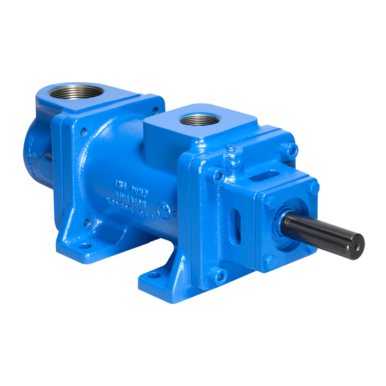
A3D SERIES PUMPS
WARNING
This Instruction Manual and General Instructions Manual SRM00046, should be read
thoroughly prior to pump installation, operation or maintenance.
Manual No. SRM00038
February 2020
Rev. 16 (20-0051)
Advertisement

Related Manuals for Circor IMO A3D Series


Summary of Contents for Circor IMO A3D Series
- Page 1 INSTRUCTION MANUAL PARTS LIST A3D SERIES PUMPS WARNING This Instruction Manual and General Instructions Manual SRM00046, should be read thoroughly prior to pump installation, operation or maintenance. Manual No. SRM00038 February 2020 Rev. 16 (20-0051)
- Page 2 FOREWORD Instruction manual covers Imo Pump Series A3D pumps. Series of pumps have been designed to meet requirements for hydraulic, distillate, lubricating, residual and crude oil applications. Because of large number of operating conditions, it is necessary to have a variety of construction and material combinations to meet job requirements.
- Page 3 X X 3D X X X X XXX X Basic Pump Modifiers Rotation A - Design Modification Blank – CW B - Carbide Seat Size 312 and Larger D- CCW D – Dampening Groove P – Short Lead Rotor Size E –...
- Page 4 STRUCTURAL LIMITS Operating conditions such as speed, fluid viscosity, inlet pressure, temperature, filtration, duty cycle, mounting, drive type, etc. are interrelated. Due to variable conditions, specific application limitations may vary from structural limitations. Equipment must not be operated without verification that operating requirements are within published capabilities as shown in appropriate pump brochure (available from local Imo Pump Division offices and representatives listed in Manual SRM000 Under no circumstances are the following structural limitations to be exceeded...
- Page 5 Table 4 LIST OF MATERIALS (FIGURES 3 THROUGH 11) ITEM PART DESCRIPTION ITEM PART DESCRIPTION Case Tube Inlet Head Lockwasher Packing Box End Cover Spacer (3) Bolt or Capscrew 038 (1) O-ring (Figure 16) Plug Spacer 006 (2) Stop Pin 042 (2) Truarc Ring (2) 007 (1)
- Page 6 Note: For disassembly of Mechanical Seal and Ball Bearing Only, follow steps 1, 2, 3, 9, 10, 11 and 13. For Reassembly of Mechanical Seal and Ball Bearing Only, Follow steps 8, 9, 10 and 11. DISASSEMBLY AND ASSEMBLY PROCEDURES (MECHANICAL SEAL PUMPS) WARNING To prevent personnel/equipment injury, power supply to pump driver must be disconnected or positively tagged out prior to starting any disassembly procedure.
- Page 7 Disassembly Procedures (Figures 3, 7, 8, 9) WARNING When inspecting/servicing shaft seal and/or bearing, power rotor can be removed as a subassembly with these components installed. Remove four (4) bearing retainer plate bolts and retainer plate, and then remove power rotor sub-assembly. If for any reason pump is disassembled further than this, it is possible idler rotor balance piston housings may fall off.
- Page 8 Remove balance piston housing (022 or 045) with O-ring (028) from case (001). Remove O-ring (028) from balance piston housing (022 or 045). Remove oil balance tube (026 or 036) with O-rings (027 or 038) from rotor housing (024) or balance piston housing (022 or 045) or inboard cover (046 or 008).
- Page 9 3. Install assembled rotor housing (024) in case (001), aligning housing (024) to receive stop pin (006). Install stop pin (006) with Dyna seal (007) in case (001). 4. (Figures 3, 7, 8, 9 and 11) Install O-ring (028) in groove of balance piston housing (022 or 045), and install balance piston housing (022 or 045) in case (001), ensuring that bore of balance piston housing (022 or 045) engages oil balance tube (026 or 036) installed in rotor housing (024).
- Page 10 11. Install bearing retainer (043 or 016) using bolts (047 or 017). Tighten bolts (047 or 017) to proper torque value listed in Table 2. 12. Install idler rotors (021) in idler bores of rotor housing (024) by engaging threads of idler rotors with threads of power rotor (044 or 063) and rotating idler rotors (021) while inserting them into rotor housing (024) bores.
- Page 11 12. (Figure 4) Remove retaining ring (008). 13. Remove power rotor (019 or 063). Removal of power rotor (019 or 063) will also remove balance piston housing (022) with O-ring (028) and oil balance tube (026). NOTE: Balance piston (020) furnished as part of power rotor (019 or 063) and is not serviced separately. 14.
- Page 12 11. Install gasket (009) and packing box end cover (003) using bolts or capscrews (004). Tighten bolts or capscrews (004) to proper torque valve listed in Table 3. Table 3 TORQUE VALVES – PACKING PUMPS Rotor Size IDP# Torque 106 (Installed in inlet) 43 ±...
- Page 17 Figure 7. A3D-218, 250, 275, & 312...
- Page 22 CIRCOR 1710 Airport Road PO Box 5020 Monroe, NC USA 28111.5020 Tel: +1 .877.853.7867 Email: cc@circor.com Web: www.circorpt.com © 2020 CIRCOR Pumps North America, LLC. All rights reserved.
Need help?
Do you have a question about the IMO A3D Series and is the answer not in the manual?
Questions and answers