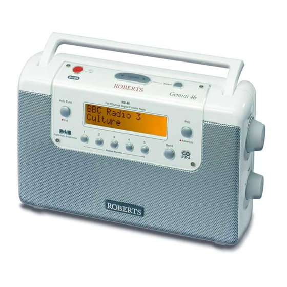
Summary of Contents for Roberts RecordR
-
Page 1: Table Of Contents
RecordR DAB/FM RDS DIGITAL PORTABLE RADIO CONTENTS Specification Block Diagram All PCB Top View All PCB Bottom View Wiring Diagram Troubleshooting Flow Chart Electrical Parts List 11-13 Mechanical Parts List Exploded Views IC Circuit Block Diagram 16-20 Semiconductor Lead Identifications... -
Page 2: Specification
Specification FM. ELECTRICAL PERFORMANCE : R.H. Model :RecordR Brand:ROBERTS Temp:25∘C Date:2011/10/11 Ver.:A Page:1/4 Condition Value Test no. Test Item Unit Input Output freq Nom. 87.5 Tuning Range S/N=6dB 90MHz Max. Sensitivity S/N=6dB 98MHz EMF dBu 106MHz 90MHz Usable Sensitivity S/N=30dB... - Page 3 Specification DAB(BAND Ⅲ) ELECTRICAL PERFORMANCE Model :RecordR Bran:ROBERTS Temp:25∘C R.H.:75% Date:2011/10/11 Ver:A Page:2/4 Test no. Test Item Condition Nom. Unit RF Freq. Range Fc : -70 dBm (Wanted channel) Fi : ≧ -38 dBm Adjacent Channel Selectivity (Unwanted channel) (Measurement to EN50248)
- Page 4 Specification SD MP3 ELECTRICAL PERFORMANCE Model :RecordR Brand:ROBERTS Temp:25∘C R.H.:75% Date:2011/10/11 Ver:A Page: 3/4 Condition Value Test no. Test Item Unit Input Output freq Nom. Playing Support playing format MP3/WMA SD capacity 16MB~8GB Sample rate 16k/32/64/128/192k bps Reading time <10...
- Page 5 Specification AUX IN ELECTRICAL PERFORMANCE Brand:ROBERTS Temp:25∘C R.H.:75% Date:2011/10/11 Ver:A Page:4/4 Model :RecordR Condition Value Test No. Test Item Unit Input Output Freq. Nom. Lim. AUX IN= 0.5Vrms /400Hz Output Power THD = 10% ( TEST : R/L SHORT ) Output=R.0 , Adjust_V.R...
-
Page 6: Block Diagram
B L OCK D IA G R A M... -
Page 7: All Pcb Top View
ALL PCB TOP VIEW... -
Page 8: All Pcb Bottom View
ALL PCB BOTTOM VIEW... -
Page 9: Wiring Diagram
WRING DIAGRAM... -
Page 10: Troubleshooting Flow Chart
TROUBLESHOOTING FLOW CHART Power can not be turned on Check whether the Pin14 Check whether the Radio Check whether the Pin1 of IC1 is VCC. is in Standby(DC IN) of IC1 is VCC. Check IC1,SW1,Q16and Check whether the Pin6 of Check Q10,Q11 GRYO-1128Module is 3.0V D15. -
Page 11: Electrical Parts List
ELECTRICAL PARTS LIST RecordR PART NO. DESCRIPTION Q'TY REMARK 1012073 CH IC UTC M2100 SOP-8 IC2,IC8, 1013620 CH IC TC 4013BFN SOL14 IC1, 1013890 CH IC PT2308 8PIN SO-P IC7, 1014660 CH IC UTC4052L-S16-R IC9, 1014980 CH IC TPA2005D1DRBR IC3,... - Page 12 ELECTRICAL PARTS LIST RecordR PART NO. DESCRIPTION Q'TY REMARK 1904020 DAB/M 1128B DAB+ RecordR 1A0220140M10 W-A/1 140(3+3) BLK 3A8AG58722W01 ADA/SW 7.5V/0.8A V BS-W 44106657T2H0 EL 106M 50V 5x7-T 105 C77,C78,C98, 44107257T2H0 EL 107M 10V 5x7-T 105 C29,C79,C81, 44107367T0H1 EL 107M 16V 6.3x7-T 105...
- Page 13 ELECTRICAL PARTS LIST RecordR PART NO. DESCRIPTION Q'TY REMARK R154,R163,R164,R165,R166, 61301104 CH RD 100KJ-0603 R28,R29,R49,R69,R70,R76,R78, R87,R115,R119,R120,R121,R122, R123,R124,R125,R126,R127,R128, R130,R132,R136,R140,R141,R142, R143,R144,R155,R304,R306,R307, R161,R148,R160, 61301105 CH RD 1MJ-0603 R61, 61301123 CH RD 12KJ-0603 R35, 61301152 CH RD 1K5J-0603 R101,R156, 61301153 CH RD 15KJ-0603 R97,...
-
Page 14: Mechanical Parts List
MECHANICAL PARTS LIST RecordR Ref no PART NO. DESCRIPTION Q'TY APP./DWG NO. REMARK 2000Q60000A FRONT RUBER KEY HOLDER A3-RD46-13 2000Q600500 TOP RUBBER KEY HOLDER A4-RD46-19 2000S800100 LCD LENS HOLDER A3-S8-01 2000S800200 LCD LIGHT LENS A4-S8-02 2100B10110A ROTARY KNOB RING A4-330-38... -
Page 16: Ic Circuit Block Diagram
IC CIRCUIT BLOCK DIAGRAM IC1 - TC4013BFN IC2 & IC8 - UTCM2100... - Page 17 IC3 - TPA2005D1DRBR IC4 - S-8550AA-M5T1G...
- Page 18 IC5 - S-80840CNMA IC6 - SCA108TAP...
- Page 19 IC7 - PT2308...
- Page 20 IC9 - UTC4052L...
-
Page 21: Semiconductor Lead Identifications
SEMUCONDUCTOR LEAD IDENTIFICATIONS Transistors 2SA1576 2SB772 2SC1623 2SC4081 BTB1424AM3 LSN42 (E: Emitter C: Collector B: Base S: Source G: Gate D: Drain) Diodes MM4148 FM5817 BZV55B3V0 BAV70N3 BZV55B4V3 (A: Anode C: Cathode) -
Page 22: Ic And Transistor Voltage Chart
IC AND TRANSISTOR VOLTAGE CHART IC1 - TC 4013BFN IC2 - UTCM2100 PIN DAB PIN DAB PIN DAB 7.35 7.35 7.35 7.35 2.57 2.57 2.57 2.57 2.59 2.59 2.59 2.59 2.59 2.59 2.59 2.59 7.40 7.40 7.40 7.40 2.59 2.59 2.59 2.59 2.59 2.59 2.59 2.59 7.40 7.40 7.40 7.40 2.57 2.57 2.57 2.57... - Page 23 IC9 - UTC4052L 2.10 2.10 2.10 2.10 3.29 2.10 2.10 2.10 2.10 2.10 2.10 2.10 2.10 2.10 2.10 2.10 2.10 2.10 2.10 2.10 2.10 2.10 2.10 2.10 2.10 4.24 4.24 4.24 4.24 Module 3.29 3.28 3.30 3.30 3.29 3.29 3.29 3.29 3.29 3.28...
- Page 24 Transistor LCD Brightness : 1 LCD Brightness : 2 LCD Brightness : 3 PIN DAB FM PIN DAB FM PIN DAB FM 0.68 0.68 0.68 0.68 1.18 1.18 1.18 1.18 0.77 0.77 0.77 0.77 0.74 0.74 0.74 0.74 1.33 1.33 1.33 1.33 1.18 1.18 1.18 1.18 0.70 0.70 0.70 0.70 1.33 1.33 1.33 1.33...
-
Page 25: Schematic Diagram
SCHEMATIC DIAGRAM...


Need help?
Do you have a question about the RecordR and is the answer not in the manual?
Questions and answers