Hansen Technologies HSC4H-N10K Specifications, Applications, Service Instructions & Parts
Gas detection sensors, monitors & alert systems
Hide thumbs
Also See for HSC4H-N10K:
Table of Contents
Advertisement
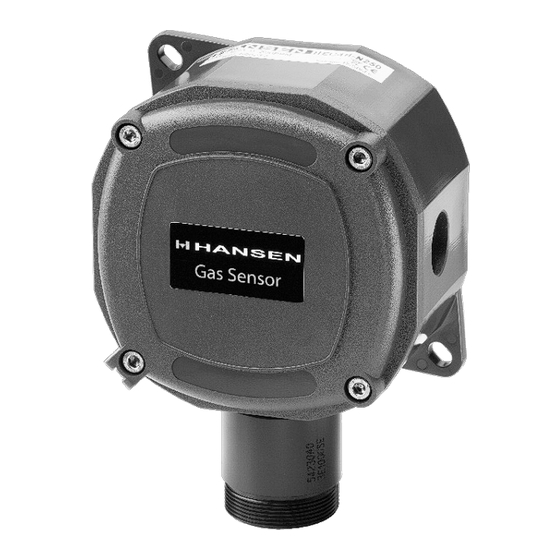
Standard Gas Sensor
INTRODUCTION
Hansen Technologies offers a complete line of industrial
quality Gas Detection Sensors, Monitors and Alert
Systems for refrigerants and other common gases. These
state-of-the-art gas detection products utilize a range of
sensing technologies to suit a given application. Available
in several configurations to meet various application
requirements with optimum accuracy and reliability.
APPLICATIONS
Hansen Gas Sensors are suitable for use in industrial
refr iger ation engine rooms, cold stor age rooms,
processing rooms, truck docks, and for relief valve vent
lines. They are also suitable for use in supermarkets,
and large institutional and commercial buildings.
Typical gas detection applications include Ammonia,
Carbon Dioxide (CO
), Hydrocarbons, HFCs, HCFCs
2
and CFCs.
ADVANTAGES
Hansen uses a wide variety of sensing technologies
including electrochemical, semiconductor and infrared
sensors to selectively detect most gases. These sensors
continuously determine the level of gas present in the
surrounding environment. The analog outputs (4-20mA
or 0-10V DC) can interface with nearly any existing
monitor, computer or PLC controller.
The sensing elements (except Basic and Extreme Gas
Sensors) are mounted externally on the enclosure. This
helps to provide quick response to potential leaks,
particularly in still air. Electronics are sealed in a NEMA4
enclosure (except Basic Gas Sensor) which protects
them from moisture, dust and the surrounding gases,
which in the case of ammonia can shorten the life of
electronics. The sensing elements are easily replaced.
Gas Sensors have built-in visual and audible alarms. An
auxiliary one amp SPDT relay output is standard. Testing
and recalibration procedures are simple.
Specifications, Applications,
Service Instructions & Parts
GAS DETECTION
SENSORS, MONITORS
& ALERT SYSTEMS
For Refrigerants and
other Common Gases
KEY FEATURES–GAS SENSORS
• Accurate, fast responding
• Linear 4-20mA or 0-10V DC output
• Audible alarm
• Power indicator
• SPDT alarm relay (Fail Safe Operation)
• 24V AC/DC low voltage power
• Shipped factory calibrated and tested
• CE approved
• CSA (Electrical Features Only)
KEY FEATURES–MONITORS
• Visual alarm
• Audible alarm
• Power indicator
• Low level alarm relay
• High level alarm relay
• Fault relay (HLM6 only)
• Economical
• CE approved
KEY FEATURES−GAS ALERT SYSTEM
• Provides local display and alarm based on
measured target gas level via gas sensor
• Visual alarm, Amber LED light
• Audible alarm (mutable)
• Power indicator, Green
• Numeric PPM reading
• Bright LED Display
• Shipped factory calibrated and tested
Bulletin A100g
JULY 2017
Advertisement
Table of Contents

Related Manuals for Hansen Technologies HSC4H-N10K

Summary of Contents for Hansen Technologies HSC4H-N10K
- Page 1 Common Gases Standard Gas Sensor INTRODUCTION KEY FEATURES–GAS SENSORS Hansen Technologies offers a complete line of industrial • Accurate, fast responding quality Gas Detection Sensors, Monitors and Alert • Linear 4-20mA or 0-10V DC output Systems for refrigerants and other common gases. These •...
- Page 2 SELECTING GAS SENSOR TYPES PORTABLE GAS DETECTION UNIT Hansen Gas Sensors are available in several types of Portable Gas Detection unit includes enclosures to match the environmental and operating the handheld unit, battery charger, conditions. e x t e n s i o n w a n d , s p a r e f i l t e r s , voltage output cable, accessories for calibration, and sensor module keeper for four sensors in a carrying...
- Page 3 GAS SENSOR LOCATION Typically ammonia sensors are mounted 12˝ – 24˝ (.3 to .5m) from the ceiling. Sensors should not be located too close Sensors should be located in an accessible area to the ceiling as hot air trapped under the ceiling may for maintenance and testing, but away from moving act to buffer the target gases from reaching the sensor.
- Page 4 GAS SENSOR SPECIFICATIONS TABLE 1 EXPLOSION BASIC STANDARD HARSH VENT LINE EXTREME PROOF 0ºF TO 122ºF 0ºF TO 122ºF -40ºF TO 105ºF -40ºF TO 122ºF -40ºF TO 122ºF -60ºF TO 105ºF OPERATING TEMPERATURE RANGE (-17ºC TO 50ºC) (-17ºC TO 50ºC) (-40ºC TO 40ºC) (-40ºC TO 50ºC) (-40ºC TO 50ºC)
-
Page 5: Stand Alone Control
GAS DETECTION SYSTEM CONFIGURATIONS There are a number of typical installation configurations to meet national and local codes. RELIEF VALVE VENT LINE Often the vent line is extended high above the ground or roof. The sensor element can be installed near the outlet of the vent line and the gas sensor electronics mounted at a convenient height for servicing. -
Page 6: Sensing Element
WIRING GAS SENSORS Hansen recommends backup of gas detection system with an uninterruptable power supply to provide battery Install the Hansen Gas Sensor in an area where operating backup in the event of a power failure. personnel can easily monitor the remote sensor. Refer to Gas Sensor Location on page 3 for suggestions on INSTALLATION proper placement of Remote Sensors. -
Page 7: Electrochemical Sensor
ELECTROCHEMICAL SENSOR (SHOWN WIRED FOR 4-20MA OUTPUT) Electro-chemical Sensor FIG. 9 AC APPLIED VOLTAGE To Monitor or PLC MULTI-WIRE SHIELDED CABLE (GROUND SHIELD AT OTHER END) Factory Default 4-20mA output Relay Output Voltage Selector - "D": 24V DC "A": 24V AC Fail Safe Relay - Relay engerized to normally open HORN... -
Page 8: Infrared Sensor
INFRARED SENSOR (SHOWN WIRED FOR 4-20MA OUTPUT) FIG. 11 A100g JULY 2017... - Page 9 SETTING ADJUSTMENTS OF SENSORS GAS SENSOR OPERATION On power up the internal relay will energize switching There are several selectable features included in the from the normally closed position to the normally open Hansen Gas Sensor. Refer to pages 7 and 8 for the position.
-
Page 10: Led Logic
LED LOGIC 3a. G a s s e n s o r s ( e x c e p t V e n t l i n e a n d S e m i - c o n d u c t o r g a s s e n s o r s ) . -
Page 11: Calibration Of Sensors
CALIBRATION OF SENSORS FIG. 12 ELECTRO CHEMICAL BOARD SHOWN (SEMI CONDUCTOR IS SIMILAR) 1 2 34 5 6 7 8 0-5V DC ZERO POT ADJUSTMENT REGULATING HORN VALVE SPAN POT ADJUSTMENT SENSING ELEMENT BOOT CALIBRATION GAS FIG C 3100-1 SENSING ELEMENT REPLACEMENT Basic Sensors Extreme Sensors The Basic Gas Sensor uses a three pin plug-in element... - Page 12 Intermittent - Relay SPDT Energized INSTALLATION INSTRUCTIONS High level alarm: The Hansen Technologies Gas Detection Monitor should be located in an accessible area, away from moving - Visual Warning Red LED equipment that could accidentally come in contact - Audible Warning Continuous with the unit.
- Page 13 Maximum Power Wiring Length to a Monitor level alarm relay using VLOW Pot. This setting applies to the six channels. 120V 230V For the high level alarm relay setting, measure the voltage System System Wire Maximum across VHIGH and GND. Set the desired high level alarm Length Length Size...
- Page 14 HLM2 WIRING DIAGRAM FIG. 13 A100g JULY 2017...
- Page 15 HLM6 WIRING DIAGRAM FIG. 14 A100g JULY 2017...
- Page 16 TROUBLESHOOTING GAS MONITORS TROUBLESHOOTING GAS SENSORS Symptom: No lights displayed on panel. Symptom: Sensor green light is off. Cause: Cause: Power failure. Check incoming line. Possible wiring fault between controller and sensor. Check power supply to Controller. Check 2. Tripped circuit breaker or blown fuse on electrical connections between the controller and the supply.
-
Page 17: Installation Dimensions
INSTALLATION DIMENSIONS INCHES (MM) HLM2 GAS ALERT SYSTEM AUDIBLE ALARM FIG. 15 FIG. 17 KEY SWITCH 7.39 (188) 5.26" HIGH LEVEL (134) ALARM RESET 6.30 HIGH LEVEL AUDIBLE ALARM (160) ALARM RESET KEY SWITCH 7.39 (188) 5.26" 10.38 (134) 6.30 (264) 4.13 (160) -
Page 18: Technical Specifications
INSTALLATION OF GAS ALERT SYSTEM The GAS Alert System is shipped factory calibrated and tested; ready to use. Mount in a location safe and easily accessible. Avoid thermal extremes and areas where falling water or condensation moisture is present. The GAS Alert System can be mounted to any solid flat surface. - Page 19 TYPICAL WIRING DIAGRAM WITH LOCAL POWER SOURCE FIG. 18 REMOTE SENSOR GREEN V +V NO COM NC External Power Supply Multi-Wire Do Not Ground Power Supply Cable Shield Shield At This End 24V AC/DC Multi-Wire EARTH GRD Cable Shield JUMPER INSTALLED. SET REMOTE SENSOR FOR DC VOLTAGE TYPICAL WIRING DIAGRAM WITH HANSEN HLM6 MONITOR FIG.
- Page 20 PLC 4 PT. ANALOG IN MODULE (CURRENT) PLC 4 PT. ANALOG IN MODULE (CURRENT) FIG. 20 *REMOTE SENSOR GREEN V +V NO COM NC Multi-Wire Cable Shield INPUT #1 Power Supply INPUT #2 24V AC/DC INPUT #3 INPUT #4 EARTH GRD ANALOG GND REMOTE SENSOR * Wiring is the same for AC or DC Power Supply.
- Page 21 TYPICAL WIRING DIAGRAM WITH LOCAL POWER SOURCE FIG. 22 A100g JULY 2017...
- Page 22 Gas Detection Test Certificate Hansen Test Certificate Product Description:_____________________ Serial Number:__________________________ Date of First Calibration:__________________ Date of Last Calibration:___________________ Type/Range of Test Gas:_________________ 1. Carry out “Bump Test” (Set delay to zero) Initial the following, encircle “OK” when completed. Power (Green LED) _______________________________ OK Visual Alarm (Red LED) _______________________________ OK...
- Page 23 HEC4H-N250 HEC4E-N250 Electrochemical 0-250 HEC4-N1K HEC4H-N1K HEC4E-N1K Electrochemical 0-1,000 HSC4-N10K HSC4H-N10K HSC4E-N10K Semiconductor 0-10,000 Note: For Explosion Proof model, substitute X for 4 in model number (i.e. HECX-N100). TABLE 7 VENT LINE Sensor Type Range (PPM) Standard to -40ºF(-40ºC) Refrigerant...
-
Page 24: Warranty
31-1026 for the 250 PPM Standard Gas Sensor, Email: sales@hantech.com Web: www.hantech.com USA ∙ Asia ∙ Europe ∙ India ∙ Latin A merica ∙ Middle East and 31-1027 for the 250 PPM Harsh/Extreme Gas Sensor. © 2011 Hansen Technologies Corporation A100g JULY 2017...
Need help?
Do you have a question about the HSC4H-N10K and is the answer not in the manual?
Questions and answers