Table of Contents
Advertisement
Quick Links
Operating Instructions
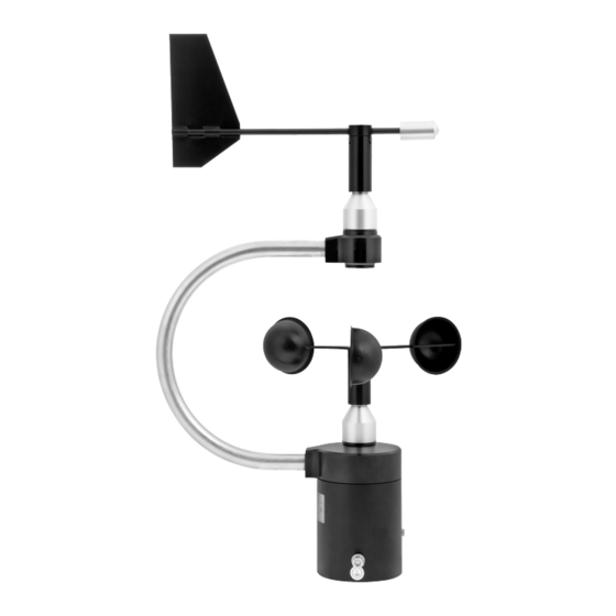
Combined Wind Sensor ARCO SDI-12
Features and Advantages ARCO SDI-12
▪ More than 150 years of experience in classical meteorology
▪ Frictionless data acquisition using non-contact measuring
principle
▪ Highest reliability and longevity due to double high-perfor-
mance bearings and special alloys
▪ Corrosion resistant surfaces for long service life
▪ Particularly low starting value (0.3 m/s)
▪ Measuring range from 0.3...55 m/s
(14582) ARCO SDI-12
▪ Quick and easy installation thanks to pipe mounting and
M12 plug connection
▪ Wind vane and 3-arm cup rotor exchangeable
▪ Increased water tightness due to water traps integrated
in the sensor
▪ SDI-12 Protocol, Version 1.4
▪ Low current consumption (< 4 mA at 12 VDC)
▪ The compact design of the sensor reduces the effort
required for components and their assembly times com-
pared to individual devices.
Operating Instructions
1
Advertisement
Table of Contents

Related Manuals for AEM LAMBRECHT meteo ARCO SDI-12


![Accessories AEM Lambrecht Meteo u[sonic]WS7 Manual](http://static.manualslib.com/public/img/no_image_60x60.svg)

Summary of Contents for AEM LAMBRECHT meteo ARCO SDI-12
- Page 1 Operating Instructions Combined Wind Sensor ARCO SDI-12 Features and Advantages ARCO SDI-12 ▪ Quick and easy installation thanks to pipe mounting and M12 plug connection ▪ More than 150 years of experience in classical meteorology ▪ Wind vane and 3-arm cup rotor exchangeable ▪ Frictionless data acquisition using non-contact measuring ▪ Increased water tightness due to water traps integrated principle in the sensor ▪ Highest reliability and longevity due to double high-perfor- ▪ SDI-12 Protocol, Version 1.4 mance bearings and special alloys ▪ Low current consumption (< 4 mA at 12 VDC) ▪ Corrosion resistant surfaces for long service life ▪ The compact design of the sensor reduces the effort ▪ Particularly low starting value (0.3 m/s) required for components and their assembly times com- pared to individual devices. ▪ Measuring range from 0.3...55 m/s (14582) ARCO SDI-12 Operating Instructions...
-
Page 2: Table Of Contents
Operating Instructions Combined Wind Sensor ARCO SDI-12 Content Introduction Start-up · General 2.1 Tools and installation material 2.2 Unpacking the sensor 2.3 Receiving inspection 2.4 Power supply 2.5 Mounting the cup rotor 2.6 Mounting the wind vane 2.7 Installation procedure (brief description) 2.7.1 Mounting the sensor 2.7.2 Power supply and signal cables 2.7.3 Safety regulations Maintenance 3.1 Regular maintenance and calibration 3.2 Visual inspections and cleaning Transport Dimensioned drawing ARCO SDI-12 Electrical connection ARCO SDI-12 SDI-12 Interface Technical data Warranty Disposal (14582) ARCO SDI-12... -
Page 3: Combined Wind Sensor Arco Sdi-12
Operating Instructions Combined Wind Sensor ARCO SDI-12 Tools and installation material Introduction No special tools are required for the pending assembly and The sensors of the ARCO series are very robust, compact and extremely reliable. During their development, special care maintenance work. All work can be carried out with standard was taken to ensure compliance with meteorological require- tools such as screwdrivers, open-end spanners and Allen keys. ments. The sensors represent the experience of more than 150 years of development and production of wind sensors at Lambrecht meteo. The system records the horizontal air flow and processes the Unpacking the sensor measured values into the meteorological parameters wind speed and wind direction. The sensor is delivered in a separate packaging, carefully The sensors and other system components are mounted in a protected against mechanical influences, in order to avoid splash-proof and dustproof metal housing. damage during transport. The housing and the measuring elements are made of cor- The packaging includes the following items: rosion-resistant aluminium alloys. Sensor housing, cup rotor · 1 Sensor ARCO SDI-12 and wind vane are anodized. · 1 Operating Instructions Accessories: (depending on order scope, packed separately) Start-up ·... -
Page 4: Mounting The Cup Rotor
Operating Instructions Combined Wind Sensor ARCO SDI-12 Mounting the cup rotor Installation procedure (brief description) The drill holes on the cup rotor are arranged in such a way The sensor is installed in three steps: that it can only be mounted in a specific, unambiguous posi- (1) Attach the cable plug to the sensor and pull the cable tion. All screws have to be used and the cup rotor or the wind through the mast if necessary. vane have to be fixed with them. This ensures the correct (2) Install the sensor on the mast, but before tightening the direction of rotation. The required Allen key is included in the screws you must align the sensor to the North. scope of delivery. (3) Connect the sensor connections for power supply and signal output. 2.7.1 Mounting the sensor The sensor is mounted on a mast piece (tube) with an outside diameter of 50 mm and an inside diameter of at least 40 mm. Before attaching the instrument with the two grub screws M8 x 12, connect the cable, lead it through the pipe and align the sensor to the north. For this purpose, an appropriate marking is attached to the instrument housing (see dimensioned drawing). Align the sen- sor to the North before tightening the screws. Halbrundschraube mit Innensechskant Please make sure that the sensor is firmly attached to the round head screw with hexagon socket... -
Page 5: Power Supply And Signal Cables
Operating Instructions Combined Wind Sensor ARCO SDI-12 Maintenance When the tip of the vane points to the reference point, the sensor can finally be attached with the two grub screws. Regular maintenance and calibration A functional test in three directions shifted each 90° is recom- mended. The sensors are designed to be very low-maintenance and for a long service life. It is recommended that you carry out regu- lar visual inspections for weather-related surface contamina- Observe all relevant safety instructions when mount- tion and cleaning if necessary. A regular visual and functional ing a sensor on a mast. check of the wind sensors is recommended. 2.7.2 Power supply and signal cables If reference measurements are required, it is essen- tial to ensure that the measured values can only be As soon as the sensor is correctly mounted and connected to compared if the measurements are carried out under the pre-assembled cable (accessory), the wires for the power... -
Page 6: Dimensioned Drawing Arco Sdi-12
Operating Instructions Combined Wind Sensor ARCO SDI-12 Dimensioned drawing ARCO SDI-12 (14582) ARCO SDI-12 Operating Instructions... -
Page 7: Electrical Connection Arco Sdi-12
Operating Instructions Combined Wind Sensor ARCO SDI-12 Electrical connection ARCO SDI-12 (14582) ARCO SDI-12 Operating Instructions... -
Page 8: Sdi-12 Interface
Operating Instructions Combined Wind Sensor ARCO SDI-12 SDI-12 Interface The communication using SDI-12 protocol via SDI-12 interface is based on the ‘SDI-12 A Serial-Digital Interface Standard for Microprocessor-Based Sensors, Version 1.4, 2017’. The ARCO SDI-12 can be used in bus mode parallel to other ARCO SDI-12. The combined wind sensor behaves like two individual bus participants with their own addresses for wind speed and wind direction. The following subset of SDI-12 commands were implemented into the ARCO SDI-12. For more information on the SDI-12 protocol, please refer to the standard documentation mentioned above or the website www.SDI-12.org. Implemented SDI-12 commands: Command Function Answer of the sensor Acknowledge Active a<CR><LF>... - Page 9 Operating Instructions Combined Wind Sensor ARCO SDI-12 Syntax Command Answer a<CR><LF> a – Sensor address a – Sensor address ! – End of command <CR><LF> – End of answer Example: Command Answer 0<CR><LF> 1<CR><LF> Send Identification - aI! The command aI! is used to ask the sensor for its model number and firmware version. Syntax Command Answer aI! a14LMGmbH1514582x1.1<CR><LF> a – Sensor address a – Sensor address I – Command "Send Identification" a14LMGmbH1514582x1.1 14 – 2 characters SDI-12 version-No. 14 = version 1.4 LMGmbH15 – 8 characters manufacturer’s (= Lambrecht meteo GmbH) 14582x – 6 characters sensor type 14582S – Wind speed 14582D – Wind direction 1.1 – Firmware version ! – End of command...
- Page 10 Operating Instructions Combined Wind Sensor ARCO SDI-12 Syntax Command Answer aAb! b<CR><LF> a – Old sensor address b – New sensor address A – Command ‘Change Address’ b – New sensor address ! – End of command <CR><LF> – End of answer Example: Command Answer 0A1! 1<CR><LF> Start Measurement - aM! The "aM!" command requests the sensor to process the available measurement data and write them to an output string. Unlike the standard sensors described in the SDI-12 documentation, the ARCO SDI-12 measures continu- ously. This is why the ARCO SDI-12 always responds with "a000". The data is therefore immediately available. This is also the reason why the ARCO SDI-12 does not send a "service request" and ignores measurement inter- ruption commands. The data can be retrieved with the command "aD0!" (see below under "Send data"). The data is not overwritten until the next "C" or "M" command and can be retrieved several times. Syntax Befehl Antwort aM! a0004<CR><LF> a – Sensor address a – Sensor address M – Command "Start Measurement"...
- Page 11 Operating Instructions Combined Wind Sensor ARCO SDI-12 Start Measurement and Request CRC - aMC! Same command as "aM!" but in addition to the generated data the sensor returns a 3-digit CRC checksum. For information on how the CRC checksum is generated, please consult SDI-12 Standard, Version 1.4, 2017, ‘ chapter 4.4.12’. Syntax Command Answer aMC! a0004<CR><LF>...
- Page 12 Operating Instructions Combined Wind Sensor ARCO SDI-12 Start Concurrent Measurement and Request - CRC aCC! Same command as "aC!" but in addition to the generated data the sensor returns a 3-digit checksum. For information on how the CRC checksum gets generated, please consult ‘SDI-12 Standard Version 1.4, 2017, chapter 4.4.12’. Syntax Command Answer aCC! a00004<CR><LF> a – Sensor address a – Sensor address C – Command ‘Start Concurrent 000 – Seconds the sensor needs until the Measurement’ measured data can be returned with "CRC" (= 0 s – Data immediately available) C – Request for transmission of the 04 – Number of provided measured data CRC checksum <CR><LF> – End of answer ! – End of command Example: Command Answer 1CC! 100004<CR><LF> Send Data - aD0! The data requested by the sensor with the commands "C" or "M" can be retrieved with the command "aD0!". The sensor uses the corresponding signs ("+" or "-") as field separators. If the data was requested with a "CC" or "MC"...
- Page 13 Operating Instructions Combined Wind Sensor ARCO SDI-12 Syntax for measurements with command "aC!" or "aM!" Command Answer aD0! a<values><CR><LF> a – Sensor address a – Sensor address D – Command ‘Send Data’ <values> – Requested data separated by 0 – Request for the data in buffer 0 resp. sign ("+" or "-") or 1 = buffer 1 ! – End of command <CR><LF> – End of answer Example: Command Answer 000004<CR><LF> 0D0! 0+0.1+0.1+0.1+0.1<CR><LF> Syntax for measurements with command "aCC!" or "aMC!" Command Answer aD0!
-
Page 14: Technical Data
Operating Instructions Combined Wind Sensor ARCO SDI-12 Technical data Warranty ARCO SDI-12 Id-No. 00.14582.070470 Please note the loss that unauthorised manipulation of the system shall result in the loss of warranty and non-liability. Changes to system components require Range Temperatures -40...+70 °C express written permission from LAMBRECHT meteo of application: Wind speed 0...55 m/s...
Need help?
Do you have a question about the LAMBRECHT meteo ARCO SDI-12 and is the answer not in the manual?
Questions and answers