Advertisement
Quick Links
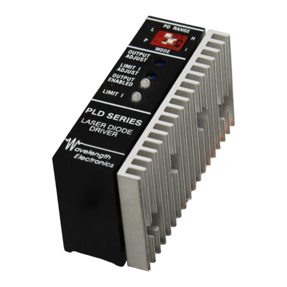
PLD Series +5V Laser Diode Drivers
______________ General Description
The PLD series of Laser Diode Drivers combines the
high performance you expect from a Wavelength component
with two distinct improvements: low voltage operation from
+5 V DC, and an Active Current Limit.
Operating from a single +5 V supply minimizes heat
dissipation. Modular packaging makes it easier to integrate
the PLD into your system. For applications that require
lasers in series, a separate laser diode power supply input
lets you provide a higher compliance voltage. The Active
Current Limit not only protects your laser diode, but ensures
that you are operating with maximum stability. When the
laser current reaches the level set by the Limit I Trimpot,
the output disables and the Limit LED and Limit Status
indicate the current limit has been reached.
Two photodiode ranges provide variable sensitivities
for optimum operation. You can maintain excellent stability
when operating in constant current, constant power, or
modulated mode. All trimpots and switches are easily
accessible and offer precision control. A slow start circuit,
mechanical shorting relay, and Active Current Limit offer
maximum protection for your laser diode even when power
is removed.
_____________ Ordering Information
PLD-500
500 mA Laser Diode Driver
PLD-5000
5 Amp Laser Diode Driver
_________________ Pin Descriptions
Call 1-406-587-4910 for technical support.
____________________ Features
• 200 mA, 500 mA, and 5 Amp models
• Single supply operation: +5 VDC
• < 20 ppm constant current stability (24 hours)
• < 0.02% constant power stability (24 hours)
• Separate Laser Diode Supply input allows for flexible
compliance voltages up to +28 VDC typical
• Manually adjust:
Setpoint & Current Limit
Constant Current or Constant Power Operation
Photodiode Sensitivity
• Remotely:
Adjust Setpoint Current with Analog Input
Enable or Disable Output
Monitor Laser Diode Current, Photodiode Current,
and Laser Diode Limit Current
Monitor Limit Status
• Supports all laser diode / photodiode pin configurations
• Safety is maximized:
Slow start circuitry
Mechanical relay protects even when power is
removed
Active Current Limit
• Integral Heatsink (Fan Assembly included with
PLD-5000)
______________ Functional Diagram
www.teamwavelength.com
PLD5000-00400-A Rev. B
1
Advertisement

Related Manuals for Wavelength Electronics PLD Series


Summary of Contents for Wavelength Electronics PLD Series
- Page 1 ______________ General Description ____________________ Features • 200 mA, 500 mA, and 5 Amp models The PLD series of Laser Diode Drivers combines the • Single supply operation: +5 VDC high performance you expect from a Wavelength component with two distinct improvements: low voltage operation from •...
- Page 2 ____________________________________________________ Laser Diode Types The following laser diode / photodiode configurations are Operating instructions for lasers of Type A or B are detailed currently manufactured - Type A, Type B, and Type C. Setup on page 8. and operation vary according to your type of laser diode. Operating instructions for Type C Lasers are detailed on Please identify which laser diode you will be using with page 12.
- Page 3 ______ POWER SUPPLY AND NOISE _________ FAN ELECTRICAL NOISE The PLD Series Laser Diode Drivers are designed for stable, PLD-5000 Only low noise operation. The power supply you select will The PLD-5000 is equipped with a +5 V fan that cools the directly affect the noise performance of the driver.
- Page 4 Supply Current PLD-200 & PLD-500: 50 mA plus max. LD current The PLD series has internal control circuitry which turns the output PLD-5000: 150 mA plus max LD current on and off depending on the voltage at pin 10. When the voltage reaches the power up trip point (+4.5 V), and the LD Enable...
- Page 5 _____________________________________________ Mechanical Specifications _________________________________________ PCB Layout Pattern - Top View...
- Page 6 ________________________________________________ Timing Characteristics Test Conditions * Symbol Parameter Test Points PLD200 - 10 Ω 6.8 µsec On Time Load PLD500 - 1.0 Ω 6.8 µsec PLD5000 - 0.1 Ω 6.8 µsec PLD200 - 10 Ω 6.8 µsec Off Time Load PLD500 - 1.0 Ω...
- Page 7 Slow Start Timing Large signal frequency response PLD-200 -0.5 -1.5 -2.5 -3.5 1000 10000 100000 Frequency (Hz) Large signal frequency response Large signal frequency response PLD-5000 PLD-500 -0.5 -0.5 -1.5 -1.5 -2.5 -2.5 -3.5 -3.5 1000 10000 100000 1000 10000 100000 Frequency (Hz) Frequency (Hz)
- Page 8 ____________________ Typical Setup for Type A or B laser diode +5V operation __________________________________ Typical Setup for Type A or B laser diode High Compliance Voltage operation...
-
Page 9: Transfer Function
____________ Operating Procedures for Type A or B laser diodes +5V operation ________________ _________________ Constant Current Mode Constant Power Mode With the Output Disabled: With the Output Disabled: (1) Configure Mode Switch to I. [switch on top of PLD] (1) Configure Mode Switch to P. [switch on top of PLD] (2) Set Limit Current: Monitor pins 5 &... - Page 10 __________ Typical Setup for Type A or B laser diode Negative Supply operation...
- Page 11 ______________________ Operating the PLDPCB with Type A & B Laser Diodes...
- Page 12 ____________________________________ Typical Setup for Type C laser diodes ________________________________________________ External Adjustments Switch Setting CAUTION: DO NOT change This switch must be set in the L position for Type C laser switch positions while the PD Range L diodes. The photodiode range is 15 - 500 µA. output is enabled;...
- Page 13 ____________________________ Operating Procedures for Type C laser diodes ______________ Constant Current Mode ________________ Constant Power Mode With the Output Disabled: With the Output Disabled: (1) Configure Mode Switch to I. [switch on top of PLD] (1) Configure Mode Switch to P. [switch on top of (2) Set Limit Current: Monitor pins 5 &...
- Page 14 _________________________ Operating the PLDPCB with Type C Laser Diodes...
- Page 15 _________________________________________________ APPLICATION NOTES Remote Status LED Monitor Calibration Circuit External Trimpot Circuit circuit A small offset may be present when Recommended circuit when an A 332 Ω resistor is in series with measuring pin 5, 7, or 8 with respect to the external trimpot is used to control the actual output.
- Page 16 The PLD series has been registered as an defective. Wavelength makes no warranty concerning OEM product. It does not comply with regulations. You...
Need help?
Do you have a question about the PLD Series and is the answer not in the manual?
Questions and answers