Table of Contents
Advertisement
Quick Links
DATASHEET AND OPERATING GUIDE
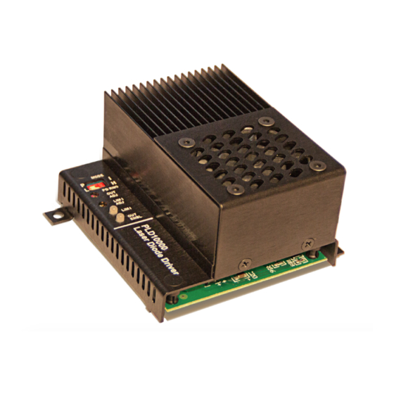
PLD10000/PLD12500
RELIABILITY YOU CAN TRUST
The PLD Series Laser Diode Drivers deliver the reliability
and performance you expect from a Wavelength Electronics
laser driver in a compact and easy-to-integrate package.
Tens of thousands of PLD drivers are deployed in laser
systems around the world, proving beyond doubt the
reliability and stability of the design.
PLD Series drivers are used for fiber laser pumping,
materials
processing,
pyrotechnic
applications, and laser diode LIV testers.
DESIGNED FOR EASY INTEGRATION
The PLD10000 is powered by a 5 V supply, and the laser
can be driven from the same supply. High-compliance
lasers can be driven by using a separate supply up to 30 V.
The PLD12500 requires two separate supplies.
CONTENTS
406-587-4910
www.teamWavelength.com
FEATURES AND BENEFITS
• Two models: 10 A and 12.5 A output current
• PLD10000 can be operated from a 5 VDC supply
• Separate power supply can be used to drive
• Product Variation allows high-compliance up to
• Constant Current or Constant Power modes
• Safety features protect your laser
• Remote Enable controls
• Optimized heatsink and fan simplifies integration
LASER SAFETY FEATURES
Built-in safety features make your product more robust
to real world operating conditions: latching current limit
switches off the output if the current limit is reached; a slow
start circuit ramps the output current; and a mechanical
shorting relay protects the laser from ESD events while the
output is switched off.
Long-term reliability means better up-time, fewer service
ignition,
industrial
calls, and more customers who are satisfied with your
products.
LOWER CURRENT MODELS
The PLD Series is available in lower current models. Go
to our website for information on the PLD200, PLD500,
PLD1250, PLD5000, and PLD6500 Laser Diode Drivers.
PAGE
2
4
5
6
7
13
18
19
20
Applies to Product Revisions A - D
© April 2020
Laser Diode Drivers
high-compliance lasers, up to 27.5 V
85V.
» Adjustable latching current limit
» Slow-start circuitry
ORDERING INFORMATION
PART NO
DESCRIPTION
PLD10000
10 A Laser Diode Driver
PLD12500
12.5 A Laser Diode Driver
Evaluation board for PLD10000 and
PLD10EV
PLD12500
USBKIT
USB Interface kit, with software
Pb
RoHS
e
Advertisement
Table of Contents

Related Manuals for Wavelength Electronics PLD10000


Summary of Contents for Wavelength Electronics PLD10000
-
Page 1: Table Of Contents
DESIGNED FOR EASY INTEGRATION LOWER CURRENT MODELS The PLD10000 is powered by a 5 V supply, and the laser The PLD Series is available in lower current models. Go can be driven from the same supply. High-compliance to our website for information on the PLD200, PLD500, lasers can be driven by using a separate supply up to 30 V. -
Page 2: Quick Connect Guide
Figure 2. PLD10000 / PLD12500 Wiring Diagram, Type A/B Lasers Ty p e C L a s e r D i o d e Ty p e A L a s e r D i o d e... - Page 3 PLD10000/PLD12500 LASER DIODE DRIVER QUICK CONNECT GUIDE, CONTINUED We recommend using a test load to configure the PLD; refer to Figure 4. When using the test load, the actual drive current can be determined by measuring the voltage drop across the resistor. Do not place an ammeter in series with the load circuit.
-
Page 4: Pin Descriptions
PLD10000/PLD12500 LASER DIODE DRIVER PIN DESCRIPTIONS Table 1. Pin Descriptions NAME PIN DESCRIPTION No Connect Photodiode cathode connection for Type C lasers only; see Figure 9 on page 10. PD Cathode Photodiode anode connection for Type A & B lasers. Photodiode feedback is required for Constant PD Anode Power-mode operation. -
Page 5: Electrical Specifications
1. Single 5 VDC supply operation is possible with PLD10000. Two supplies are required for PLD12500. See page 7 for Dual power supply operation. 2. Use two supplies with PLD10000 when driving high-compliance lasers, or when lower drive current noise is required. PLD12500 requires two supplies. -
Page 6: Safety Information
PLD10000/PLD12500 LASER DIODE DRIVER SAFETY INFORMATION THEORY OF OPERATION The PLD10000 and PLD12500 drivers are controlled SAFE OPERATING AREA — DO NOT EXCEED linear-mode current sources: they deliver the current INTERNAL POWER DISSIPATION LIMITS commanded by the setpoint. The current source continually... -
Page 7: Operating Instructions
Linear-regulated or low-noise switching power supplies can be used. We recommend using power supplies with noise specifications suitable for your application. For single-supply operation (PLD10000 only): • 5 VDC power supply rated for 1.1-times the maximum laser diode current, plus 250 mA for the electronics... - Page 8 If you are using the PLD10EV evaluation board to familiarize Output Laser Connection Current Monitor yourself with operating the PLD10000 or PLD12500, follow Use 14 AWG minimum Select these instructions to configure the jumpers on the evaluation Figure 5. PLD10EV Evaluation Board board.
- Page 9 PLD10000/PLD12500 LASER DIODE DRIVER Short pin 16 to pin 19 when analog input is not used. Analog Input PD Anode Optional External 4,5,6 LD Cathode Setpoint (0 to 5 V) Common 7,8,9 LD Anode (Low Current) 0.1 µF Closed = Output Enabled...
- Page 10 PLD10000/PLD12500 LASER DIODE DRIVER Short pin 16 to pin 19 when analog input is not used. Analog Input PD Anode Optional External 4,5,6 LD Cathode Setpoint (0 to 5 V) Common 7,8,9 LD Anode (Low Current) 0.1 µF Closed = Output Enabled...
- Page 11 PLD10000/PLD12500 LASER DIODE DRIVER ONBOARD ADJUSTMENTS AND CONTROLS CALCULATE THE MONITOR VOLTAGES Onboard controls are on the top of the PLD and must be Refer to the datasheet for your laser to determine the set according to the operation mode. The controls are maximum forward current, and calculate the LIM I Monitor illustrated in Figure 10.
- Page 12 PLD10000/PLD12500 LASER DIODE DRIVER ADJUST THE OUTPUT CURRENT SETPOINT— ONBOARD CONTROL To increase the output current, turn the onboard trimpot clockwise; turn counter-clockwise to decrease output current. While adjusting the output current, measure the voltage on pin 18, I Monitor. Use the transfer function listed in Table 2 to determine the output current from the monitor voltage.
-
Page 13: Additional Technical Information
PLD10000/PLD12500 LASER DIODE DRIVER ADDITIONAL TECHNICAL CHANGE THE PHOTODIODE RANGE, TYPE A & B LASERS INFORMATION The photodiode current range and transfer function can be This section includes useful technical information on these adjusted using an external resistor. This feature is useful... - Page 14 PLD10000/PLD12500 LASER DIODE DRIVER CHANGE THE ANALOG INPUT MODULATION IMPORTANT INFORMATION ON GROUNDING TRANSFER FUNCTION Some laser diodes connect the laser anode or cathode to the case. Pay particular attention to grounding to ensure The Analog Input Modulation transfer function can be safe operation of the PLD and laser.
- Page 15 • Changing the controller input voltage REVISION A & B TIMING CHARACTERISTICS Table 4 and Table 5 describe the timing characteristics of Revisions A and B of the drivers. Table 4. Output Timing, PLD10000 Revision A TURN-ON SLOWSTART TURN-OFF TIME...
- Page 16 PLD10000/PLD12500 LASER DIODE DRIVER OUTPUT ON/OFF AND CURRENT LIMIT TIMING Figure 18 through Figure 20 illustrate the the output turn-on delay, slowstart turn-on/off time, and current limit response. Figure 18. Output Turn-On Delay Figure 19. Output On/Off-Time Figure 20. Current Limit Response ©...
- Page 17 25.0 27.5 30.0 Voltage Drop (V) Refer to the Wavelength Electronics website for the most Figure 21. SOA for PLD10000 up-to-date SOA calculator for our products. The online tool is fast and easy to use, and also takes into consideration operating temperature.
-
Page 18: Troubleshooting
PLD10000/PLD12500 LASER DIODE DRIVER TROUBLESHOOTING PROBLEM POTENTIAL CAUSES SOLUTIONS Driver will not switch on Improperly configured power Carefully check the wiring diagram according to Table 3. Make sure the supply polarity of the power supply is correct. Output will not enable... -
Page 19: Mechanical Specifications
PLD10000/PLD12500 LASER DIODE DRIVER MECHANICAL SPECIFICATIONS 3.050 77.47 0.15 3.81 0.40 10.16 Direction of airflow 2.450 62.23 1.100 27.94 3.20 81.28 1.03 26.15 0.30 2.75 69.85 7.62 3.35 85.09 1.93 48.9 0.20 0.60 15.2 0.50 12.7 1.41 35.9 Figure 23. PL10000 / PLD12500 Mechanical Dimensions 4.500... -
Page 20: Certification And Warranty
SAFETY There are no user-serviceable parts inside this product. Return the CERTIFICATION product to Wavelength Electronics for service and repair to ensure that safety features are maintained. Wavelength Electronics, Inc. (Wavelength) certifies that this product met its published specifications at the time of shipment.
Need help?
Do you have a question about the PLD10000 and is the answer not in the manual?
Questions and answers