Table of Contents
Advertisement
Quick Links
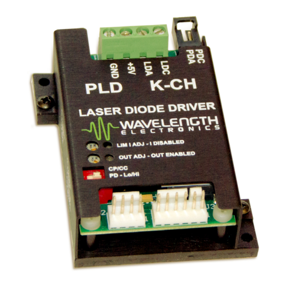
DATASHEET AND OPERATING GUIDE
RELIABILITY YOU CAN TRUST
The PLDxK-CH Series Laser Diode Drivers deliver the
reliability and performance you expect from a Wavelength
Electronics laser driver in a compact and easy-to-integrate
package.
APPLICATIONS
Tens of thousands of PLD drivers are deployed in particle
counters,
manufacturing
scanners, fiber aligners, and other laser systems, proving
beyond doubt the reliability and stability of the design.
CONTENTS
406-587-4910
www.teamWavelength.com
PLDxK-CH Series
Chassis Mount Laser Diode Drivers
vision
systems,
wavefront
Applies to Product Revisions
PLD5K-CH & PLD10K-CH: Rev A - D
PLD12.5K-CH: Rev A - B
FEATURES AND BENEFITS
• Models: 5 A, 10 A, 12.5 A
• 5 A and 10 A models operate from a single 5 VDC
supply; 12.5 A model requires two supplies
• Separate power supply can be used to drive
high-compliance lasers up to 28 V
• Product Variation allows high-compliance up to
85 V.
• Constant Current or Constant Power modes
• Safety features protect your laser
» Adjustable latching current limit
» Slow-start circuitry
• Local and Remote Enable controls
DESIGNED FOR EASY INTEGRATION
The PLDxK-CH drivers operate from a single 5 V power
supply. To accommodate high compliance lasers, or
multiple stacked lasers, the PLDxK-CH laser diode drivers
allow the laser to be driven from a separate power supply
up to 30 V.
LASER SAFETY FEATURES
Built-in safety features make your product more robust
to real world operating conditions: latching current limit
switches off the output if the current limit is reached; slow
start circuit ramps the output current; and a mechanical
shorting relay protects the laser from ESD events.
Long-term reliability means better up-time, fewer service
calls, and more customers who are satisfied with your
products.
ORDERING INFORMATION
PAGE
2
PART NO
4
PLD5K-CH
6
PLD10K-CH
7
PLD12.5K-CH
8
WCB308
15
21
23
24
© April 2020
DESCRIPTION
5 A Laser Diode Driver
10 A Laser Diode Driver
12.5 A Laser Diode Driver
Power / LD Cable Set
e
Pb
RoHS
Advertisement
Table of Contents

Related Manuals for Wavelength Electronics PLD K-CH Series


Summary of Contents for Wavelength Electronics PLD K-CH Series
-
Page 1: Table Of Contents
DATASHEET AND OPERATING GUIDE PLDxK-CH Series Chassis Mount Laser Diode Drivers FEATURES AND BENEFITS • Models: 5 A, 10 A, 12.5 A • 5 A and 10 A models operate from a single 5 VDC supply; 12.5 A model requires two supplies •... -
Page 2: Quick Connect Guide
Enabled Status (LD STATUS) Output Enable (LD ENABLE) Modulation Input (ANALOG IN) Photodiode Voltage (PDV - type C lasers only) Visit the Wavelength Electronics website for the most PIN 1: COMMON Limit Current Monitor (LMON) Photodiode Current Monitor (PMON) accurate, up-to-date, and easy to use SOA calculator: Current Monitor (IMON) www.teamwavelength.com/support/design-tools/soa-ld-calculator/... - Page 3 PLDXK-CH SERIES LASER DIODE DRIVER QUICK CONNECT GUIDE, CONTINUED We recommend using a test load to configure the PLDxK-CH; refer to Figure 4. When using the test load, the actual drive current can be determined by measuring the voltage drop across the resistor.
-
Page 4: Pin Descriptions
PLDXK-CH SERIES LASER DIODE DRIVER PIN DESCRIPTIONS Table 1. Pin Descriptions CABLE NAME PIN DESCRIPTION COLOR Connector H1; Screw terminal header; WCB308 Power/LD Cable available separately Power Supply Ground. High current return for the +5 V power supply input. Black Supply voltage to control electronics. - Page 5 PLDXK-CH SERIES LASER DIODE DRIVER Table 2. Current Output Monitor, Limit Monitor, Photodiode Current Monitor, and Analog Input Transfer Functions FUNCTION MODE LABEL PLD5K-CH PLD10K-CH PLD12.5K-CH LMON, Current Limit Setpoint Monitor CC / CP 2 A / V 4.6 A / V 5 A / V LMON IMON, Output Current Monitor...
-
Page 6: Electrical Specifications
PLDXK-CH SERIES LASER DIODE DRIVER ELECTRICAL SPECIFICATIONS PARAMETER SYMBOL VALUE UNIT NOTE ABSOLUTE MAXIMUM RATINGS Supply Voltage (H1:2) +5 V 5.0 to 5.5 See Power Supply Requirements on page 8 Consult Safe Operating Area calculator for supply Supply Voltage, (H1:3) voltages >... -
Page 7: Safety Information
PLDXK-CH SERIES LASER DIODE DRIVER SAFETY INFORMATION THEORY OF OPERATION The PLDxK-CH Series drivers are controlled current SAFE OPERATING AREA — DO NOT EXCEED sources: they deliver the current commanded by the INTERNAL POWER DISSIPATION LIMITS setpoint. The current source continually monitors the actual output current, compares it to the setpoint, and adjusts the Before attempting to operate the PLDxK-CH driver, it is current if there is a difference between the two signals. -
Page 8: Operating Instructions
PLDXK-CH SERIES LASER DIODE DRIVER OPERATING INSTRUCTIONS SAFE OPERATING AREA AND THERMAL DESIGN CONSIDERATIONS The PLDxK-CH requires no external electronic components. SOA charts are included in this datasheet for quick reference, but we recommend you use the online tools instead. The driver is first configured for local control in order to set the drive current limit. - Page 9 PLDXK-CH SERIES LASER DIODE DRIVER WIRING THE PLD5K-CH AND PLD10K-CH Figure 5. Type A & B Laser Diode, Single 5 VDC Power Supply PLD5K-CH and PLD10K-CH * A twisted-pair Power and LD Cable Short J3:5 to J3:1 when is available separately (WCB308) analog input is not used.
- Page 10 PLDXK-CH SERIES LASER DIODE DRIVER WIRING THE PLD5K-CH AND PLD10K-CH (CONTINUED) Figure 7. Type C Laser Diode; PLD5K-CH and PLD10K-CH * A twisted-pair Power and LD Cable Short J3:5 to J3:1 when is available separately (WCB308) analog input is not used. J3:5 J1:2 Analog Input...
- Page 11 PLDXK-CH SERIES LASER DIODE DRIVER WIRING THE PLD12.5K-CH Figure 9. Type A & B Laser Diode, Using Two Power Supplies; PLD12.5K-CH * A twisted-pair Power and LD Cable Short J3:5 to J3:1 when is available separately (WCB308) analog input is not used. J3:5 J1:1 Analog Input...
- Page 12 PLDXK-CH SERIES LASER DIODE DRIVER WIRING THE PLD12.5K-CH (CONTINUED) Figure 11. Type A & B Laser Diode, Negative Power Supply Operation; PLD12.5K-CH * A twisted-pair Power and LD Cable Short J3:5 to J3:1 when is available separately (WCB308) analog input is not used. J3:5 J1:1 Analog Input...
- Page 13 PLDXK-CH SERIES LASER DIODE DRIVER ONBOARD ADJUSTMENTS AND CONTROLS CALCULATE THE MONITOR VOLTAGES Onboard controls are on the top of the PLDxK-CH and Refer to the datasheet for your laser to determine the must be set according to the operation mode. The controls maximum forward current, and calculate the current limit are illustrated in Figure 12.
- Page 14 PLDXK-CH SERIES LASER DIODE DRIVER ADJUST THE OUTPUT CURRENT SETPOINT— CURRENT LIMIT CIRCUIT TRIGGER AND RESET ONBOARD CONTROL If the PLDxK-CH detects current limit, the output will switch off and the I DISABLED LED on the top of the unit To increase the output current, turn the onboard trimpot will illuminate red and the LD Status voltage will drop to clockwise;...
-
Page 15: Additional Technical Information
PLDXK-CH SERIES LASER DIODE DRIVER ADDITIONAL TECHNICAL CHANGE PHOTODIODE RANGE, TYPE A & B LASERS INFORMATION The photodiode current range and transfer function can be adjusted by adding an external resistor. This feature is useful This section includes useful technical information on these when the photodiode current of your laser falls in a range topics: that does not allow maximum measurement sensitivity on... - Page 16 PLDxK-CH driver. Figure 15 illustrates a simple circuit. It is critical that the PLDxK-CH Driver is properly grounded. If the PLDxK-CH Driver is used with a Wavelength Electronics ANALOG temperature controller, you may need to INPUT use two separate power supplies that float independently of each other.
- Page 17 PLDXK-CH SERIES LASER DIODE DRIVER CABLE LENGTHS AND HIGH CURRENT MONITOR CALIBRATION CIRCUIT The length and gauge of cable from the power supply or A small offset may be present when measuring the PMON, to the laser diode can impact performance. The resistance IMON or LMON voltage with respect to the actual output.
- Page 18 PLDXK-CH SERIES LASER DIODE DRIVER Two configurations are explained below. These two NEGATIVE LASER POWER SUPPLY WIRING configurations accomplish the same function, which is Connecting the laser anode to ground will give the best to provide a 5 V bias across the electronics. Since the low-noise performance.
- Page 19 PLDXK-CH SERIES LASER DIODE DRIVER OUTPUT ON/OFF AND CURRENT LIMIT TIMING PARALLEL PLDS FOR HIGHER CURRENT Figure 24 through Figure 26 illustrate the output turn-on Multiple PLDxK-CH drivers can be connected in parallel to delay, output rise and fall times, and current limit response. drive higher current.
- Page 20 25.0 27.5 30.0 Voltage Drop (V) Refer to the Wavelength Electronics website for the most Figure 27. SOA for PLD5K-CH up-to-date SOA calculator for our products. The online tool is fast and easy to use, and also takes into consideration operating temperature.
-
Page 21: Troubleshooting
PLDXK-CH SERIES LASER DIODE DRIVER TROUBLESHOOTING PROBLEM POTENTIAL CAUSES SOLUTIONS Driver will not switch on Improperly configured power Carefully check the wiring diagram according to Table 3. supply Output will not enable Remote Enable signal is not Refer to the LD Enable specifications in Table 1 and make sure your correct input enable signal is correct. - Page 22 PLDXK-CH SERIES LASER DIODE DRIVER CABLING SPECIFICATIONS MONITOR CABLE -- WCB304; INCLUDED WITH PLDXK-CH MOLEX PART #10-11-2043 5.0” BLACK WHITE GREEN OVERALL LENGTH 24” I/O CABLE -- WCB305; INCLUDED WITH PLDXK-CH MOLEX PART #10-11-2063 5.0” BLACK ORANGE WHITE GREEN BLUE SHIELD WIRE OVERALL LENGTH 24”...
-
Page 23: Mechanical Specifications
PLDXK-CH SERIES LASER DIODE DRIVER MECHANICAL SPECIFICATIONS Ø 0.13 0.70 3.18 17.78 2 Holes 2.35 59.69 2.10 53.34 1.85 46.99 0.15 2.60 3.81 66.04 2.90 73.66 Direction for Recommended Airflow 1.12 0.94 28.45 23.88 0.19 2.90 4.83 73.66 3.19 80.93 Figure 30. -
Page 24: Certification And Warranty
CERTIFICATION AND WARRANTY There are no user-serviceable parts inside this product. Return the CERTIFICATION product to Wavelength Electronics for service and repair to ensure that safety features are maintained. Wavelength Electronics, Inc. (Wavelength) certifies that this product met its published specifications at the time of shipment.
Need help?
Do you have a question about the PLD K-CH Series and is the answer not in the manual?
Questions and answers