Advertisement
Quick Links
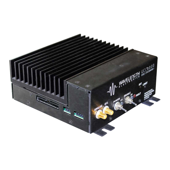
Low Noise QCL Driver
Minimize spectral drift, center wavelength jitter,
and linewidth
GENERAL DESCRIPTION:
The QCL1500 includes patented circuitry
for driving Quantum Cascade Lasers (QCLs)
where electronic noise, coupled through the
laser, can affect measurements.
This is an OEM controller, designed to be
integrated into fi eld deployed systems or used
on a benchtop. It operates from dual DC power
supplies. Low noise can be achieved even with
certain switching power supplies.
An onboard Current Setpoint trimpot allows a DC
bias to be set. Its signal sums with a remote Analog
Input signal that can be negative or positive.
Safety: An onboard trimpot sets the current limit
as you monitor the setting - without driving current
through the QCL.
Brownout, reverse voltage,
and overvoltage protection isolates the QCL from
power supply failures. An Overtemp Fault signal
minimizes the chance of failure due to overheated
electronics. An onboard Enable Switch controls
when current can fl ow to the QCL. A remote
Enable signal can also be used.
Applications:
High
sensing in biomedical, imaging, spectroscopy,
remote
sensing,
military,
aerospace and materials processing industries.
To optimize noise performance in your application,
current range can be adjusted. Other product
variations are available.
factory with your requirements at 406-587-4910
or quietqcl@teamwavelength.com.
1
Covered by U.S. Patents 6,696,887; 6,867,644 and
7,176,755. Licensed from Battelle Memorial Institute.
© 2010
1
ideal
performance
chemical
communications,
Please contact the
QCL1500-00400-D
November, 2010
FEATURES:
• Off the shelf models at 500 mA, 1 A, 1.5 A
• Can be delivered in other current ranges up to 2 A
- with noise minimized for your QCL
• Compliance voltage up to 16 V
• Low noise: < 1A RMS over 100 kHz bandwidth
(graphs on page 5)
• Analog Input Setpoint sums with onboard trimpot
• Safety: Current Limit, 1.25 second ON delay with
100 msec current ramp, Remote Enable signal,
brown out, reverse & over voltage, overtemp
protection circuits
• Remote Power On and Enable signals are TTL
compatible and fully isolated
• Adjustable Current Limit with monitor
• Local power & enable / disable switches
• Protection relay shorts output when current is
disabled
• Shielded from external interference
• Constant Current Mode operation
• 3 dB bandwidth 2 -3 MHz
• Status Outputs can drive LEDs
• Small Package 6.55 x 5.5 x 2.3"
• Compatible with P/N PTCxxK-CH precision
temperature controllers
• Accessories include cables and power supplies to
simplify integration.
Ordering Information
QCL500
500 mA Low Noise QCL Driver
QCL1000
1 A Low Noise QCL Driver
QCL1500
1.5 A Low Noise QCL Driver
QCL2000
Product Variations are available up to 2 A
QCL-SMA-ADAPT
Convert signal pins to SMA connectors
WCB310
Low Noise Cable: SMA to SMA
WCB311
QCL 20 pin connector with cables
WCB312
QCL Dual Power Supply wiring kit
PWRPAK-24V
24 VDC Switching Power Supply
NOISE SCAN
Noise Characterization Scan
PAGE 1
e
Pb
RoHS
www.teamWavelength.com
Advertisement

Related Manuals for Wavelength Electronics QCL500


Summary of Contents for Wavelength Electronics QCL500
- Page 1 Other product variations are available. Please contact the factory with your requirements at 406-587-4910 Ordering Information or quietqcl@teamwavelength.com. QCL500 500 mA Low Noise QCL Driver QCL1000 1 A Low Noise QCL Driver QCL1500 1.5 A Low Noise QCL Driver...
- Page 2 PAGE 2 QUICK CONNECT Figure 1 Quick Connect ON = HI OFF = LO ENABLED = HI No Connect DISABLED = LO No Connect Remote Power On - * Optically isolated from ground Remote Power On + (user-configurable) Remote Enable - * Remote Enable + QCL Enable Status Power Status...
- Page 3 PAGE 3 ELECTRICAL AND OPERATING SPECIFICATIONS ABSOLUTE MAXIMUM RATINGS RATING SYMBOL VALUE UNIT Positive Supply Voltage + 25 Volts DC Negative Supply Voltage - 25 Volts DC Output Current (See SOA Chart [1]) 500, 1000, 1500 Internal Power Dissipation, +25˚C, no air 10, 16 , 21 Watts (model dependent) Operating Temperature, case [2]...
-
Page 4: Qcl500 Qcl1000 Qcl1500
Analog In Input Impedance Sum of (trimpot + AI) < 0 V or > 5.5 V Analog In Damage Threshold Analog In Transfer Function QCL500 A / V Analog In Transfer Function QCL1000 A / V Analog In Transfer Function... - Page 5 Average Current Noise How noise measurements are made is detailed in Density - nA / SHz (100 kHz BW) WEI’s Low Noise Measurement Protocol Technical QCL500 Note. QCL1000 QCL1500 Figure 3 Typical Current Noise Density and Cumulative Noise Current (RMS) Measured with short cables, on unshielded benchtop, 10 ...
- Page 6 PAGE 6 ELECTRICAL AND OPERATING SPECIFICATIONS, continued Figure 4 Typical Square Wave Response 10 kHz 600 kHz Figure 5 Typical Limit Circuit Response, Limit set well below setpoint There is a slight (2%) overshoot when the driver is operating in current limit (with the limit value Limit Limit...
- Page 7 PAGE 7 PIN DESCRIPTIONS (left to right) PIN NO. PIN DESCRIPTION FUNCTION No connect Reserved No connect Not used Remote Power On - Return for Remote Power On signal - optically isolated Remote Power On + OFF = LO (< 0.3 V). ON = HI (> 3 V). Toggle to reset a protection circuit error.
- Page 8 PAGE 8 OPERATING PROCEDURES 1. Thermal Design Verify that the Internal Heat Dissipation for your application does not exceed the maximum allowed. The Safe Operating Area chart details the location of this limit. Online, at http://www.teamwavelength.com/support/calculator/soa/soald.php, choose the model of QCL driver you will be using. Enter your power supply and QCL characteristics to determine internal power dissipation with your design.
- Page 9 PAGE 9 OPERATING PROCEDURES, continued 2. Confi gure control for Local Only, Local & Isolated Remote, or Local & Grounded Remote. Wire Remote Signals. The Remote Power On and Remote Enable signals interact with the onboard switches. A DIP switch on the bottom of the board confi...
- Page 10 PAGE 10 OPERATING PROCEDURES, continued 3. Wire Test Load To become familiar with the QCL driver operation, we recommend that you wire a test load fi rst. This can be as simple as a resistor. We recommend a metal fi lm, TO-220, 50 W, as a typical test load. Two vendor numbers are: Caddock MP850-10.0-1% (Digikey part number MP850-10.0-F-ND) or Ohmite TCH35P10R0JE (Digikey part number TCH35P10R0JE-ND) The QCL driver is not designed to operate with the QCL pins shorted.
- Page 11 QCL1500 - 2.0 V on the Current Monitor pin, equivalent current is (2.0 V * 0.6 A / V) or 1.2 A. QCL500 - 5 V on the Limit Monitor pin, equivalent limit current is (5 V * 0.09 A / V) or 450 mA.
-
Page 12: Figure 11
EXAMPLES: QCL500 - Want 400 mA Output Current, equivalent voltage is (0.400 A / 0.2 A / V) or 2 V. QCL1000 - Want 950 mA Output Current, equivalent voltage is (0.950 A / 0.4 A / V) or 2.375 V. - Page 13 PAGE 13 APPLICATION NOTES OPTIMIZE NOISE Noise is specifi c to each application. Here are a few suggestions for reducing system noise: • Buy the right controller for your QCL. The lower the maximum current capacity, the lower the current noise. Contact the factory for a custom range. •...
- Page 14 PAGE 14 APPLICATION NOTES CABLE ADAPTER IMPROVE BANDWIDTH Minimize cable length to improve bandwidth. If you will not be mounting the QCL driver on a Sometimes twisting wires for signal pairs will PCB, you can use Molex high pressure housing also improve bandwidth.
- Page 15 PAGE 15 APPLICATION NOTES FUSE REPLACEMENT Remove the baseplate to access the fuses. Two 5 A, 5 x 20 mm, SLO-BLOW fuses can be replaced. There are no other user serviceable parts inside the QCL driver. Change fuses in an ESD safe zone. WCB311 20 PIN CONNECTOR WIRING DIAGRAM Pin 1 is indicated on the molded plastic connector, or by the lack of wires in Pins 1 &...
- Page 16 PAGE 16 MECHANICAL SPECIFICATIONS Dimensions are in inches [mm]. Tolerance is ± 5%. www.teamWavelength.com © 2010 QCL1500-00400-D...
- Page 17 PAGE 17 PCB MOUNTING GUIDELINES The QCL driver needs to be mounted by the baseplate mounting holes, not supported by the solder joints. The solder joints are not meant for mechanical support. .038 20 PLS 6.000 6.550 6.55 5.550 1.900 .100 .849 .281...
- Page 18 PAGE 18 MECHANICAL SPECIFICATIONS PWRPAK-24V Diagram courtesy TDK-Lambda - data subject to change Additional use and mounting guidelines are available in the PWRPAK-24V datasheet. www.teamWavelength.com © 2010 QCL1500-00400-D...
- Page 19 PAGE 19 APPENDIX A SAFE OPERATING AREA & AIRFLOW REQUIREMENTS Caution: Do not exceed the Safe Operating Area (SOA). Exceeding the SOA voids the warranty. An online tool is available for calculating Safe Operating Area at: http://www.teamwavelength.com/support/calculator/soa/soald.php. To determine if the operating parameters fall within the SOA of the QCL driver, the maximum voltage drop across the driver and the maximum current must be plotted on the SOA curves.
- Page 20 PAGE 20 SAFE OPERATING AREA & AIRFLOW REQUIREMENTS The charts on this page can be used to determine if your design falls within the Safe Operating Area (SOA) for the QCL series driver that you are using. For an example of how to use these charts, reference the previous page. There is also an online Safe Operating Area calculator available at: http://www.teamwavelength.com/support/calculator/soa/soald.php www.teamWavelength.com...
- Page 21 LIFE SUPPORT POLICY: WARRANTY SERVICE: As a general policy, Wavelength Electronics, Inc. does For warranty service or repair, this product must not recommend the use of any of its products in life be returned to the factory. An RMA is required...
Need help?
Do you have a question about the QCL500 and is the answer not in the manual?
Questions and answers