
Related Manuals for Hayward TC Series


Summary of Contents for Hayward TC Series
- Page 1 HAYWARD FLOW CONTROL TC SERIES TRUE UNION BALL CHECK VALVE INSTALLATION, OPERATION AND MAINTENANCE INSTRUCTIONS Hayward Flow Control www.haywardflowcontrol.com 1-888-HAY-INDL (1-888-429-4635) TCIS Rev D 5/15/18 Pg. 1 of 11...
- Page 2 WARNING The TC Series True Union Ball Check Valve is intended for use in liquid service only. Do not attempt to use this valve for controlling air or gases. Use of this product in air or gas service may result in product damage, property damage, personal injury, or even death.
-
Page 3: Installation
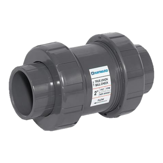
BODY (1) ASSY NUTS (2) FIGURE 1 NOTE Hayward TC Series True Union Ball Check Valves with standard balls are uni-directional. There is a flow arrow marked on the valve to indicate proper flow direction. 1.2.1. Remove valve from packaging. - Page 4 1.2.4.4. Flange Connections: 1.2.4.4.1. NOTE: When provided with flanges, TC Series True Union Ball Check Valves are provided with an end connection sub- assembly, consisting of an end connector, solvent cemented to a flange, with an assembly nut for connection to the valve.
-
Page 5: Startup And Operation
WARNING The TC Series True Union Ball Check Valve is intended for use in liquid service only. Do not attempt to use this valve for controlling air or gases. Use of this product in air or gas service may result in product damage, property damage, personal injury, or even death. -
Page 6: Maintenance
Piping system should be properly aligned prior to valve installation. 3.1.8.2 Never install valve into system that must be forcibly separated in order to allow space for body. This will apply undue loading on the valve body Hayward Flow Control www.haywardflowcontrol.com 1-888-HAY-INDL (1-888-429-4635) TCIS Rev D 5/15/18... -
Page 7: Troubleshooting
Check that valve was not in service or operated at temperatures above or below recommended operating temperature. No flow thru valve Valve installed backwards Remove valve and install with correct flow direction. Hayward Flow Control www.haywardflowcontrol.com 1-888-HAY-INDL (1-888-429-4635) TCIS Rev D 5/15/18 Pg. 7 of 11... -
Page 8: Product Specifications
Published operating requirements are based on testing of new valves using clean water at 70°F. Valve performance is affected by many factors including fluid chemistry, viscosity, specific gravity, flow rate, and temperature. These should be considered when sizing systems using Hayward products. Temperature (ºC) - Page 9 CPVC PVDF Temperature (°F) Chart 2: Operating pressures at elevated temperatures for PVC and CPVC 2-½”thru 6” size and for valves in PP and PVDF materials Hayward Flow Control www.haywardflowcontrol.com 1-888-HAY-INDL (1-888-429-4635) TCIS Rev D 5/15/18 Pg. 9 of 11...
- Page 10 6.0 PARTS LIST: END CONNECTOR O-RING (2) ASSY NUTS (2) BALL SEAL RETAINER BODY O-RING SQUARE CUT SEAL SEAL RETAINER END CONNECTOR (2) Hayward Flow Control www.haywardflowcontrol.com 1-888-HAY-INDL (1-888-429-4635) TCIS Rev D 5/15/18 Pg. 10 of 11...
-
Page 11: Warranty Terms And Conditions
ANY IMPLIED WARRANTY OF MERCHANTABILITY OR FITNESS FOR A PARTICULAR PURPOSE. The warranty set forth above is the only warranty applicable to Hayward products and in no event shall Hayward be liable for any delay, work stoppage, cartage, shipping, loss of use of equipment, loss of time, inconvenience, loss of profits of any direct or indirect incidental resulting from or attributable to a breach of warranty.
Need help?
Do you have a question about the TC Series and is the answer not in the manual?
Questions and answers