
Related Manuals for GMV NGV-EK


Summary of Contents for GMV NGV-EK
- Page 1 English NGV EK VALVE NGV-EK V ALVE ANUAL NSTALLATION SE AND AINTENANCE 1 0991 491 EN VAILABLE WITH TANK TYPE GL, F1, T2, T3, GL Dry, F1 Dry...
- Page 2 1 0991 491 EN - 23.08.2016 NGV-EK V ALVE ANUAL 2 / 45 1.00 NSTALLATION SE AND AINTENANCE WARNING - IMPORTANT GMV Spa declines all responsibility in case you do not follow the instructions in this document. Particularly, may cause safety problems to the system and to the passengers, if you do not respect the...
- Page 3 ONNECTION SCHEMAS FOR SOFT STOP 2.6 C ONNECTIONS TO THE TERMINAL AND TO THE MOTOR 2.6.1 S UBMERGED MOTOR 2.6.2 D RY MOTOR 3 NGV-EK CONTROL BOARD (CARD) 3.1 F EATURES 3.1.1 H OW TO INTERFACE 3.1.1.1 M AIN CONFIGURATIONS 3.1.1.2 S TOP MODE 3.1.2 S...
- Page 4 All rights reserved. Any kind of exploitation in any form and by any means is forbidden without a written permission of GMV Spa. GMV Spa, within technical or manufacturing progress, reserves the right to modify parts or this manual without notice.
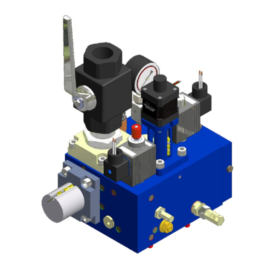
- Page 5 Shut-off valve / Screw for rupture valve test Shut-off valve for pressure gauge exclusion Regulator of the ram pressure (only 2:1 acting jacks) Regulator of the pressure safety valve (hand pump) Interface box (NGV-EK / Control panel) Chamber of the VRP Inlet chamber VB outlet chamber...
- Page 6 1 0991 491 EN - 23.08.2016 NGV-EK V ALVE ANUAL 6 / 45 1.00 NSTALLATION SE AND AINTENANCE VSMA Lowering valve manual / electrical 0 GENERAL SECTION 0.1 INTRODUCTION INFORMATIONS 0.1.1 DEFINITIONS In this manual are used the definitions in EN81-2: Safety rules for the construction and installation of lifts,...
- Page 7 Ride comfort comparable to a VVVF electric and no consumption in standby mode Maintenance speed adjustable (*) Maximum value reached under optimal conditions and in combination with other products GMV The driving option NTERNAL EMPERATURE The choice to immediate savings, interfaced with all, existing and...
- Page 8 Can be extended with an additional device in order to manage the uncontrolled movement of the car (amendment A3). The NGV-EK01 card coupled to a power unit with NGV-EK valve, is advantageous because : Can be installed on any system in which the control panel, both existing and new, does not meet the requirements to control of a power unit with standard NGV-A3 valve.
- Page 9 1 0991 491 EN - 23.08.2016 NGV-EK V ALVE ANUAL 9 / 45 1.00 NSTALLATION SE AND AINTENANCE when excited directs the flow towards the valve, allowing then to be able to supply the motor (by-pass) pump with the VB spool closed. The valve is energized after the VB opening and it is de- energized at the end of Soft Stop or when occurs an advance interruption of the manoeuvre.
- Page 10 1 0991 491 EN - 23.08.2016 NGV-EK V ALVE ANUAL 10 / 45 1.00 NSTALLATION SE AND AINTENANCE WARNING Needful prerequisite of the control panel, when the system is outside of the doors unlocking zone, is that it does not send commands to the card and/or the motor / pump.
- Page 11 1 0991 491 EN - 23.08.2016 NGV-EK V ALVE ANUAL 11 / 45 1.00 NSTALLATION SE AND AINTENANCE 2 INSTALLATION OPERATIONS WARNING During the installation never exclude the safety devices and never connect the motor/pump directly to the power supply 2.1 HYDRAULIC CONNECTIONS...
- Page 12 1 0991 491 EN - 23.08.2016 NGV-EK V ALVE ANUAL 12 / 45 1.00 NSTALLATION SE AND AINTENANCE 2.1.2.2 CONNECTION WITH A RIGID PIPE • Cut at 90° the head of the pipe with a saw (do not use a pipe-cutter) •...
- Page 13 Alarm 1A@250Vac WARNING The control panel, when receive a FAULT signal from the NGV-EK card (Connector X1 output 10,11,12), should not send commando to the valve and/or the motor/pump In FAULT condition the motor/pump group should NOT be active WARNING To detect the unintended movement of the car the system use the circuit required by paragraph 7.7.1...
- Page 14 1 0991 491 EN - 23.08.2016 NGV-EK V ALVE ANUAL 14 / 45 1.00 NSTALLATION SE AND AINTENANCE 2.5.1 MAIN SCHEMA 18÷30V~ 18÷30V~ 24÷40 V µ 2200÷4700 F...
- Page 15 1 0991 491 EN - 23.08.2016 NGV-EK V ALVE ANUAL 15 / 45 1.00 NSTALLATION SE AND AINTENANCE 2.5.2 CONNECTION SCHEMAS FOR SIGNALS AND POWER Scheme Mode 0, 1 Scheme Mode 2 M 0,1 MP-ISO CARD CARD VMP CV1 VML CV2 CV2 AUX CV3 CV3...
- Page 16 1 0991 491 EN - 23.08.2016 NGV-EK V ALVE ANUAL 16 / 45 1.00 NSTALLATION SE AND AINTENANCE 2.5.3 CONNECTION SCHEMAS FOR SOFT-STOP Soft Stop Scheme mode 1 CFS = Upward stop switch 24...48V / 0V CARD 0V / 16...48V...
- Page 17 1 0991 491 EN - 23.08.2016 NGV-EK V ALVE ANUAL 17 / 45 1.00 NSTALLATION SE AND AINTENANCE 2.6 CONNECTIONS TO THE TERMINAL AND TO THE MOTOR 2.6.1 SUBMERGED MOTOR 230-400V 400-690V ∆ Y- ∆ 230V ∆ 400V ∆ Y- ∆...
- Page 18 NGV-EK01 SC- SC1 SC2 SC3 SC- VMP CV1 VML CV2 CV2 AUX CV3 CV3 OS1OS2 OS3LS LD 3.1 FEATURES The hardware features of the card NGV-EK are: DESCRIPTION VALUE ONTROL PANEL INTERFACE Power supply of the card 24V= -5%, +20% 20…180(230) Vdc/(Vac)
- Page 19 Different interfacing modes are provided with the various existing configurations of the control panel, settable by the PT01 programmer through the menu.In case of failure to supply directly the NGV-EK card with the required voltage, you must use a suitable power supply, type-ALM 03, capable to provide the correct voltage deriving it from the valve supply voltage available in the control panel.
- Page 20 1 0991 491 EN - 23.08.2016 NGV-EK V ALVE ANUAL 20 / 45 NSTALLATION SE AND AINTENANCE 1.00 3.2 CONNECTIONS 3.2.1 CONTROL PANEL INTERFACE The interfacing with the control panel is made via removable terminal connectors defined as follows: Connettor X1, step 5,0 mm Pos.
- Page 21 1 0991 491 EN - 23.08.2016 NGV-EK V ALVE ANUAL 21 / 45 1.00 NSTALLATION SE AND AINTENANCE 3.2.2 VALVE INTERFACE The valve interfacing is made by these connections: Connettor X7, step 5,0 mm Pos. Mark Features Description 24…60Vdc/ac, Output down direction command 80…180Vdc (230Vac)
- Page 22 3.2.4 JUMPERS Jumper J4, Boot (µchip) Connector for factory programming of the flash memory of the µ Chip. Can only be performed by GMV technicians, properly trained and authorized, using dedicated software. BAT1 Jumper J6 (to set connector X13) Pos.
- Page 23 1 0991 491 EN - 23.08.2016 NGV-EK V ALVE ANUAL 23 / 45 1.00 NSTALLATION SE AND AINTENANCE Connector for extensions (Encoder, …) BAT1 3.2.6 USER INTERFACE Slot J3, µSD (serial SPI) Slot for µSD memory cards (serial SPI)
- Page 24 1 0991 491 EN - 23.08.2016 NGV-EK V ALVE ANUAL 24 / 45 NSTALLATION SE AND AINTENANCE 1.00 6.11 Soft stop : distance Leveller FUN11 Function 11 : Inhibition of stop signal By-pass valve Upward Mono/bistable (NO/NC) Downward command Motor / pump...
- Page 25 1 0991 491 EN - 23.08.2016 NGV-EK V ALVE ANUAL 25 / 45 1.00 NSTALLATION SE AND AINTENANCE 3.4 DECELERATION DISTANCES [m/s] RAL,S Extra Slow Slow Standard Fast 0,00 < V ≤ 0,15 0,19 0,15 0,13 0,12 0,15 < V ≤ 0,40...
- Page 26 1 0991 491 EN - 23.08.2016 NGV-EK V ALVE ANUAL 26 / 45 NSTALLATION SE AND AINTENANCE 1.00 when full inserted and you must press up to the unlock in order to remove it. \NGV The µSD memory could be always hot-plugged.
- Page 27 The storage of operating parameters on µ SD uses two different ways: • factory, can be performed only by PC (only by GMV) and allows you to store in the directory ... \ fact, the parameters saved during the test of the valve, available for a recovery by the user.
- Page 28 ALVE ANUAL 28 / 45 NSTALLATION SE AND AINTENANCE 1.00 4.1 ADJUSTMENT OF THE OVERPRESSURE VALVE (OPP/MPS) NGV-EK 1” ¼ PT01 ALVE ROGRAMMER VSMA To adjust the overpressure valve: 1. Refer to the hydraulic circuit of the NGV valve 2.
- Page 29 1 0991 491 EN - 23.08.2016 NGV-EK V ALVE ANUAL 29 / 45 1.00 NSTALLATION SE AND AINTENANCE 4.2 RAM PRESSURE ON THE VSMA ADJUSTMENT NOTE Adjustment possible only with systems 2:1 To adjust the ram pressure on the VSMA : 1.
- Page 30 1 0991 491 EN - 23.08.2016 NGV-EK V ALVE ANUAL 30 / 45 NSTALLATION SE AND AINTENANCE 1.00 As required from the rule EN81-2 must be respected:the following points The system shall be provided with a means /switch able to detect...
- Page 31 1 0991 491 EN - 23.08.2016 NGV-EK V ALVE ANUAL 31 / 45 1.00 NSTALLATION SE AND AINTENANCE For safety it’s required that the test take place behind closed doors. Then proceed as follows: 1. Put at all landings the sign “Out of service”...
- Page 32 1 0991 491 EN - 23.08.2016 NGV-EK V ALVE ANUAL 32 / 45 NSTALLATION SE AND AINTENANCE 1.00 Slow UP max Dec.Profile High DN max Start Delay DN PARAMETERS Slow DN max Offset V0 UP Nom. Speed V0 4.10 Offset V0 DN Int.Speed V1...
- Page 33 1 0991 491 EN - 23.08.2016 NGV-EK V ALVE ANUAL 33 / 45 1.00 NSTALLATION SE AND AINTENANCE Alarm 01: Pstat. Min Slow Speed ▼ 00: xxxxxxxxxxxx xx.x bar x.xxx m/s NGV-EK01 Alarm 02: Pstat.max Relev. Speed 00: xxxxxxxxxxxx xx.x bar x.xxx m/s...
- Page 34 1 0991 491 EN - 23.08.2016 NGV-EK V ALVE ANUAL 34 / 45 NSTALLATION SE AND AINTENANCE 1.00 1.7 FLY TIME Fly time of the lift Total Dec->Stop Start->Dec 1.7.1 TOTAL Total time of the lift travel [s] XXX.X S 1.7.2 START->DEC...
- Page 35 DOWNWARD levelling space XXX MM adjustment in INTERMEDIATE speed (0 ÷ 600 mm) - 5 - SETTINGS Data entered by GMV, run control during the installation of the system NGV-EK01 5-SETTINGS 5.1 LIFT RATIO Ratio of the lift system (1:1; 2:1; 3:1) 5.2 JACK DIAM.
- Page 36 1 0991 491 EN - 23.08.2016 NGV-EK V ALVE ANUAL 36 / 45 NSTALLATION SE AND AINTENANCE 1.00 6.2 INT.SPEED V1 Intermediate speed [m/s] (15 ÷ 75 % x Nominal Speed) X.XX M/S 6.3 INS.SPEED V2 Inspection speed (0.15 ÷ 0.63 m/s) X.XX M/S...
- Page 37 1 0991 491 EN - 23.08.2016 NGV-EK V ALVE ANUAL 37 / 45 1.00 NSTALLATION SE AND AINTENANCE 8.4 OUTPUT 41-42 Active function on output 41-42. Every function is identified by a code FUNXXXX described into Output Programmable Functions Chart As default the output are set up with this functions: (for other functions see §...
- Page 38 NGV-EK01 µ SD <> PARAM 11.1 SAVE USER Save the NGV-EK card parameters into the file archive of the µSD ENT = START [directory: \usr] 11.2 LOAD USER Load the NGV-EK card custom parameters from the file archive of the <USER LIST>...
- Page 39 1 0991 491 EN - 23.08.2016 NGV-EK V ALVE ANUAL 39 / 45 1.00 NSTALLATION SE AND AINTENANCE S3 (VB Open) S2 (VB Close) S1 (VRP) 5.5.1 FAULT ANALYSIS Fault Possible cause Possible solution Increase power voltage by 01: SUPPLY LOW...
- Page 40 1 0991 491 EN - 23.08.2016 NGV-EK V ALVE ANUAL 40 / 45 NSTALLATION SE AND AINTENANCE 1.00 Contact S2 (VBC) did not opened sensor to the correct position. (see 19: S2 NOT OPEND when VB opens 6.5). If the problem persist on the...
- Page 41 1 0991 491 EN - 23.08.2016 NGV-EK V ALVE ANUAL 41 / 45 1.00 NSTALLATION SE AND AINTENANCE Ball valve seal Labels, signs and schemes Overall check-up 6.3 MAINTENANCE SCHEDULES What to do: (see image) Valve gaskets seals At the end of installation, and during check-...
- Page 42 1 0991 491 EN - 23.08.2016 NGV-EK V ALVE ANUAL 42 / 45 NSTALLATION SE AND AINTENANCE 1.00 Disconnect the hand pump (M) LEGENDA: Mount the pressure gauge (MAN). M - Pompa a mano di prova Ball valve seal N - Rubinetto pompa a mano O - Manometro pompa Close the ball valve (R/S) and open the pressure gauge shut off (6).
- Page 43 1 0991 491 EN - 23.08.2016 NGV-EK V ALVE ANUAL 43 / 45 1.00 NSTALLATION SE AND AINTENANCE 6.4.1 SENSOR S1 6.4.2 SENSOR S2 6.4.3 SENSOR S3 1. Using the programmer PT01 select the function 9.8 S3 tuning and activate it pressing ENT 2.
- Page 44 1 0991 491 EN - 23.08.2016 NGV-EK V ALVE ANUAL 44 / 45 NSTALLATION SE AND AINTENANCE 1.00 7 CERTIFICATES 7.1 TYPE EXAMINATION 7.2 CONFORMITY UNI EN 12016:2008 - UNI EN 12015:2005, EN 50178:1997 - IEC 60974-1:2007, UNI EN 81-2:2010 §F.6.3.1.1.a) - CEI EN 60068-2-6:2008,...
- Page 45 1 0991 491 EN - 23.08.2016 NGV-EK V ALVE ANUAL 45 / 45 1.00 NSTALLATION SE AND AINTENANCE APPARECCHIATURE FLUIDODINAMICHE E COMPONENTI PER ASCENSORI GMV SPA , 10 - 20016 PERO – M Azienda NOCCHI ILANO TALY TEL. +39 02 33930.1 - FAX +39 02 3390379...
Need help?
Do you have a question about the NGV-EK and is the answer not in the manual?
Questions and answers