Table of Contents
Advertisement
Quick Links
Advertisement
Table of Contents

Subscribe to Our Youtube Channel
Related Manuals for CoolAutomation CoolPlug


Summary of Contents for CoolAutomation CoolPlug
- Page 1 Quick Installation Guide CoolPlug / CooLinkHub HVAC Bridge Version 2.7.0...
-
Page 2: Table Of Contents
FJ (Fujitsu/General) - Option 4 - 3 wires to adapter Guidelines Connecting CoolPlug ME (Mitsubishi Electric) How to pair and connect CoolPlug to CooLinkHub ME (Mitsubishi Electric) Option 1 – [1] [2] Rebuilding the wireless mesh network ME (Mitsubishi Electric) Option 2 – CN-105... - Page 3 Safety Guidelines, Warnings and Cautions Read and understand the following guidelines to ensure safe installation. Failure to follow these WARNINGS may result in injury or death This equipment is to be installed by an accredited electrician When DIN rail mounting, fix the devices properly to the DIN rail or equivalent technical person, as per these installation following the instructions below.
- Page 4 DO NOT INSTALL the COOLINKHUB or COOLPLUG IN THE FOLLOWING LOCATIONS: Do not allow children to play with the CoolPlug or CooLinkHub. Do not disassemble, modify, or repair the CoolPlug or Where mineral oil mist or oil spray or vapor is produced, such CooLinkHub.
-
Page 5: Coolplugs And Coolinkhub
HVAC unit. CoolPlug connects directly to the HVAC indoor unit on one end, and to the CooLinkHub on the other. CooLinkHub - aggregates multiple CoolPlug devices... -
Page 6: Wired Connection - Pbus (Plugbus) Topology
Wired connection - PBUS (PlugBus) Topology The PBUS is CoolAutomation's proprietary Bus, running on a shielded twisted pair cable (20-24AWG). The PBUS utilizes daisy chain network topology. No loops are allowed. Up to 10 CoolPlugs can be connected to a single CooLinkHub. -
Page 7: Wireless Connection Topology
Up to 10 CoolPlug devices can be connected to a single CooLinkHub. The recommended distance between each of the two devices (CoolPlug/ CooLinkHub) is up to 20m (50 ft) line of sight. Please note, that concrete walls, ceilings and other types of obstacles or noise caused from electro-magnetic fields (generated by power cables or other sources), can significantly impact signal strength and will result in reduced distance. -
Page 8: Coolplug Models
CoolPlug Models CoolPlug models are HVAC manufacturer specific. Each CoolPlug has a small round sticker with letters on its back (DK, DKS, etc.) indicating the HVAC manufacturer that the CoolPlug is compatible with. CoolPlug Model HVAC Vendor Cable included Terminals/comments... - Page 9 What is in the box? CoolPlug CooLinkHub • CoolPlug device • CooLinkHub device • Flat plastic back plate • USB cable • DIN rail plastic back plate • RS-232 cable (optional) • 2 sticky bands • RJ45 Ethernet cable • 2 magnets * Cables - only for specific brands.
-
Page 10: Connecting Coolplug Dk (Daikin)
CoolPlug, respectively. Please refer to the PBUS connection diagram on page Optional: Connect the Wired Remote Controller (WRC) in parallel with CoolPlug. * The connection is nonpolar. ** Master/Slave configuration will be done by the CoolPlug automatically. - Page 11 Connecting the CoolPlug to the Daikin unit Connect the S21 cable supplied with the CoolPlug, between the CoolPlug RJ-11 connector and the S21 port on the indoor unit's PCB. Use Daikin's installation manual for the location of the S21 socket on the Daikin indoor PCB.
- Page 12 Connect the S21 cable supplied with the CoolPlug, between the CoolPlug Indoor connector (bottom S21 socket on CoolPlug) and the S21 port on the indoor unit's PCB. Use Daikin's installation manual for the location of the S21 socket on the Daikin indoor PCB.
- Page 13 DK (Daikin) – When connecting to S403 using KRP980B1 Connecting the CoolPlug to the Daikin unit. Connect the S21 cable supplied with the CoolPlug, between the CoolPlug Indoor connector (bottom S21 socket on CoolPlug) and the S21 port on KRP980B1 adapter's PCB.
- Page 14 CooLinkHub, to the corresponding [-], [1] and [2] terminals on the CoolPlug. Please refer to the PBUS connection diagram on page Optional: Connect the wired remote to the WRC socket on the CoolPlug. The cable is supplied with the WRC.
-
Page 15: Connecting Coolplug Pn/Sa/To
Please refer to the PBUS connection diagram on page Optional: Connect the wired remote to the WRC socket on the CoolPlug. The cable is supplied with the WRC. * The connection is nonpolar. ** Master/Slave configuration will be done by the CoolPlug automatically. - Page 16 Connecting the CoolPlug to the Panasonic units with CAPRA connectors Connect the CAPRA cable (supplied with the CoolPlug) between the CoolPlug RJ-11 connector (CN - CNT) and the CN - CNT port on the indoor unit’s PCB. Use HVAC manufacturer’s installation manual for location of CN - CNT connector on the indoor unit’s PCB.
-
Page 17: Connecting Coolplug Fj (Fujitsu/General)
* For indoor units that work with APG000 or compatible WRC models. ** Room temperature will not be shown if original WRC is not connected. *** Reset power of the Fujitsu Indoor unit, once the CoolPlug is installed. **** Master/Slave configuration will be done by the CoolPlug automatically. -
Page 18: Fj (Fujitsu/General) - Option 2: 3 Wires
Fujitsu Wired Remote Controller (WRC). * For indoor units that work with EZ-099 or compatible type wired remote controllers. ** Reset power of AC indoor unit, once the CoolPlug is installed. *** Room temperature will not be presented if original WRC... -
Page 19: Fj (Fujitsu/General) - Option 3: 2 Wires
Optional: Connect the Wired Remote Controller (WRC) in parallel with CoolPlug. * Reset power of AC indoor unit, once the CoolPlug is installed. ** If indoor unit has V1, V2, V3 terminals, connect the CoolPlug and WRC to terminals V1, V2. - Page 20 Connecting the CoolPlug to the Fujitsu UTY-XCBXZ1/UTY- XCBXZ2/UTY- TWBXF adapter Connect the FJ-003 cable supplied with the CoolPlug to [W1], [BY], [RY] ports on the the CoolPlug side, and the 5 pin cable connector to the UTY-XCBXZ1/UTY-XCBXZ2/ UTY- TWBXF adapter.
-
Page 21: Connecting Coolplug Me (Mitsubishi Electric)
Connect the Wired Remote Controller (WRC) in parallel with the CoolPlug. * The connection is nonpolar. ** Master/Slave configuration will be done by the CoolPlug automatically. Both PBUS and HVAC line have the same terminal labels [1] and [2] , but they belong to different networks. - Page 22 Please refer to the PBUS connection diagram on page Optional: For connecting the Wired Remote Controller (WRC) in parallel mode with CoolPlug, the CN105 Splitter is required. (This part can be purchased from CoolAutomation). ** Master/Slave configuration will be done by the CoolPlug automatically.
-
Page 23: Connecting Coolplug Mh (Mitsubishi Heavy)
** Master/Slave configuration will be done by the CoolPlug automatically. *** Some of the wall mounted series do not have terminals for WRC. To have CoolPlug connected to this unit, an additional (SC-BIK-E) adapter might be required. This adapter can be purchased locally from any Mitsubishi Heavy distributor. -
Page 24: Connecting Coolplug Ht (Hitachi)
Connecting CoolPlug HT (Hitachi) Connecting the CoolPlug to the Hitachi indoor unit (for VRF indoor units only) Connect the CoolPlug's [A] [B] terminals to the [A], [B] terminals on the indoor unit accordingly. Connecting the CoolPlug to the CooLinkHub Wireless Mode: Check the devices were paired successfully. -
Page 25: Connecting Coolplug Lg (Lg)
Connecting the CoolPlug to the Indoor unit Connect the cable (supplied with the CoolPlug) between the CoolPlug [Y] [B] [R] and CN-REMO on the indoor unit's PCB or on the cable. Use the HVAC manufacturer's installation manual to locate the required terminals on the indoor. -
Page 26: Connecting Coolplug Md (Midea)
Figure 1 – CoolPlug powered by CooLinkHub Connecting the CoolPlug to the Indoor unit Connect the CoolPlug's [X] [Y] [E] terminals to the [X] [Y] [E] terminals on the indoor unit accordingly. Note, that [E] terminal in CoolPlug stands for electrical COMMON and is located on the right side of CoolPlug's terminal. - Page 27 Figure 2 – CoolPlug WRLS - with individual external power supply...
-
Page 28: Coolplug Grts (Gree )
Connect the short cable (supplied with the CoolPlug) to 2 connectors on the WRC ports. Connect the long WRC cable (supplied with the WRC) to the other end of the short cable on one side, and to the CoolPlug on the other. - Page 29 Connecting CoolPlug GRTS (Gree) Gree GRTS - Option 2: When WRC Connects to Indoor Unit Cable Connecting the CoolPlug HVAC line to the Gree Indoor Unit Connect the cable (supplied with the CoolPlug) between the CoolPlug Indoor connector and the connector on the indoor unit's cable.
-
Page 30: Gree - Option 3 - 2 Wires
Connecting CoolPlug GRTS (Gree) Gree GRTS - Option 3: 2 wires Connecting the CoolPlug HVAC line to the Gree Indoor Unit Connect the CoolPlug's [H1] [H2] terminals to terminals [H1] and [H2] on the indoor unit PCB accordingly. Use the HVAC manufacturer's Installation Manual for the location of the connection terminals on the indoor PCB. -
Page 31: Connecting Coolplug Gree Gmv5 (Gr)
Connecting CoolPlug GR (Gree VRF GMV5) Gree VRF GMV5 only Connecting the CoolPlug HVAC line to the Gree Indoor Unit Connect the CoolPlug's [H1] [H2] terminals to terminals [H1] and [H2] on the indoor unit PCB accordingly. Use the HVAC manufacturer's Installation Manual for the location of the connection terminals on the indoors PCB. -
Page 32: Connecting Coolplug Samsung (Sm)
CooLinkHUB to the corresponding [-], [1] and [2] terminals on the CoolPlug, respectively. Please refer to the PBUS connection diagram on page Optional: Connect WRC in parallel with CoolPlug. * The connection is nonpolar. ** Master/Slave configuration will be done by the CoolPlug automatically. -
Page 33: Samsung - Option 2: 4 Wires
CoolPlug, respectively. Please refer to the PBUS connection diagram on page Optional: Connect WRC in parallel with the CoolPlug. * The paired connections(F3/F4 and V1/V2) are nonpolar. ** Master/Slave configuration will be done by the CoolPlug automatically. -
Page 34: Bms & Controlapp
Connecting Home Automation, BMS & Control App... -
Page 35: Control App
Control App Connect the device to the Internet for registration and setup. Option A – Automatic process Option B – Manual process Scan the QR code from the type label to auto fill-in all Open: https://control.coolremote.net/device-registration. the CooLinkHub details for the Control App. Enter the CooLinkHub SN number and PIN code, printed on the sticker. -
Page 36: Coolplug Operation
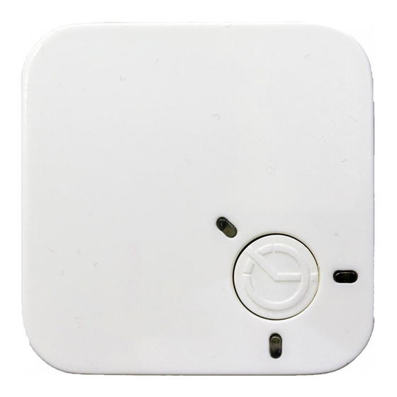
CoolPlug Operation CoolPlug Indicators The three LEDs that surround the CoolPlug's push- button provide information about the CoolPlug configuration and status. The CoolPlug is powered on, the Firmware version is displayed by flashing LEDs followed by the operational state of the system. - Page 37 'Short' press on the CoolPlug push-button. Toggling the HVAC ON/OFF Long Press Toggle the HVAC state ON/OFF with one 'Long' press for 2-3 seconds on the CoolPlug push-button. Resetting the CoolPlug Short Press + Long Press Reset the CoolPlug with one 'Short' press followed by one 'Long' press on the CoolPlug push-button.
-
Page 38: Guidelines
To successfully pair the CooLinkHub Wireless (WRLS) to the CoolPlug Wireless (WRLS) they must be in line of sight proximity one to the other (no more than three meters). The CoolPlug WRLS is powered from the HVAC terminal. It can also be powered via USB during the setup process (either from a PC or the CooLinkHub WRLS). - Page 39 On the CoolPlug WRLS, press the button five times (take 1 second between consecutive presses). A fast blinking red light is displayed while pairing to the CooLinkHub WRLS. Red LED status indication: • Constantly ON – CoolPlug WRLS is not paired.
-
Page 40: Rebuilding The Wireless Mesh Network
Press the OK button. Upon successful reconnection, the expected number of CPs is displayed on the screen in L5 GXXX (as in the image below). * To reconnect devices, no actions need to be performed on the CoolPlug WRLS devices. -
Page 41: Mounting The Coolplug
The wires can be inserted through the hole in the center of the cover or from the side as shown. On a DIN Rail Use the DIN rail back plate of the CoolPlug to attach it to the DIN rail utilizing magnets. - Page 42 Need more help? Visit us at: https://coolautomation.com/support...
Need help?
Do you have a question about the CoolPlug and is the answer not in the manual?
Questions and answers