
Related Manuals for CoolAutomation CooLinkBridge Series


Summary of Contents for CoolAutomation CooLinkBridge Series
- Page 1 HVAC Control Made Simple CooLinkBridge for Zone Controllers User Manual Version 2.0 19/8/2019 Document Number: 2.0 Contact: info@coolautomation.com...
-
Page 2: Table Of Contents
CoolAutomation CooLinkBridge Zone Controller Introduction Table of Contents 1. Introduction ............................1 Compatibility ..................... 1 2. Overview ............................. 2 Conventions ...................... 2 Revisions History ....................2 Related Documentation ..................3 Acronyms and Abbreviations ................3 3. System Layout and Connectivity ..................... 4 CooLinkBridge DKZ .................. -
Page 3: Introduction
CoolAutomation CooLinkBridge Zone Controller Introduction Introduction This User Manual (UM) provides the information necessary, for installers and integrators, to effectively use the CooLinkBridge for connecting with zone controllers of multiple manufacturers. Compatibility CooLinkBridge Zone controller Models Notes Model Manufacturer CooLinkBridge... -
Page 4: Overview
CoolAutomation CooLinkBridge Zone Controller Overview Overview The CooLinkBridge enables integration of the Zone Controller device with Home Automation and BMS (Building Management System) controllers. When controlling the Zone Controller device through the CooLinkBridge, the user is able to control AC unit and each zone as if it was a separate Indoor unit. -
Page 5: Related Documentation
CoolAutomation CooLinkBridge Zone Controller Overview Related Documentation Document Name Document Location and/or URL https://coolautomation.com/lib/doc/CoolMasterNet/manual/CoolM BACnet integration guidelines asterNet-BACnet-guidelines.pdf Modbus Integration Guidelines http://coolautomation.com/lib/doc/CoolMasterNet/manual/CoolMa sterNet-Modbus-guidelines.pdf Table 2 - Referenced Documents Acronyms and Abbreviations Acronym Literal Translation Data Terminal Equipment GPIO General Purpose Input / Output... -
Page 6: System Layout And Connectivity
CoolAutomation CooLinkBridge Zone Controller System Layout and Connectivity System Layout and Connectivity The following sub-sections provide details on the different connectivity options of the system and how to use the various functions of the CooLinkBridge. CooLinkBridge has multiple models, with different interfaces, for connecting to the different auxiliaries. - Page 7 CoolAutomation CooLinkBridge Zone Controller System Layout and Connectivity 3.1.2.2 RS232 I/O Connector The RS232 Interface in CooLinkBridge is available from the RS232 I/O connector. An adapter cable routes RS232 signals to the DB9 connector according to the table below: RS232/IO Pin...
- Page 8 CoolAutomation CooLinkBridge Zone Controller System Layout and Connectivity By default, terminals MOD A and MOD B are used as an RS485 Interface line for DTE connection. CooLinkBridge DKZ supports the following RS485-based protocol: • Modbus RTU (Slave mode) • BACnet MSTP 3.1.2.4...
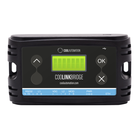
- Page 9 CoolAutomation CooLinkBridge Zone Controller System Layout and Connectivity Characteristic Value Default TCP/IP port 10102 Table 9 - ASCII I/F IP server characteristics 3.1.2.6 LCD Screen The CooLinkBridge is equipped with an alphanumeric 8x2 characters LCD that presents important device parametric and status information.
-
Page 10: Coolinkbridge Izn
CoolAutomation CooLinkBridge Zone Controller System Layout and Connectivity CooLinkBridge IZN 3.2.1 Power The CooLinkBridge can be powered by one of the following methods: • AC/DC adapter via VDC+ and VDC- terminals • 12-24V DC from HVAC or other equipment via VDC+ and VDC- terminals •... - Page 11 CoolAutomation CooLinkBridge Zone Controller System Layout and Connectivity 3.2.2.2 RS232 I/O Connector The RS232 Interface in CooLinkBridge is available from the RS232 I/O connector. An adapter cable routes RS232 signals to the DB9 connector according to the table below: RS232/IO Pin...
- Page 12 CoolAutomation CooLinkBridge Zone Controller System Layout and Connectivity • Modbus RTU (Slave mode) • BACnet MSTP 3.2.2.4 ETH Connector The CooLinkBridge incorporates an IEEE 802.3 compatible 10/100 Mb/s Ethernet port via an RJ45 connector. Below are the main port features.
- Page 13 CoolAutomation CooLinkBridge Zone Controller System Layout and Connectivity (1) ETH network connection status: Disconnected, Connected (2) CoolRemote cloud connection status: Not connected, Connected, Connected, communication in progress (3) HVAC line communication status: RX, TX (4) IP address (if acquired) and S/N are displayed (1 min toggle) (5) Indoor unit UID (L2.001 on this picture)
-
Page 14: Installation Guidelines
CoolAutomation CooLinkBridge Zone Controller Installation Guidelines Installation Guidelines Daikin DKZ 4.1.1 How to connect Wired Remote Controller Figure 3 - System Wiring Diagram Follow the procedure below to connect the CooLinkBridge DKZ to the Zone Controller and Indoor Unit: •... -
Page 15: Functional Limitations
CoolAutomation CooLinkBridge Zone Controller Installation Guidelines 4.1.2 Functional Limitations The following limitations should be considered when installing and integrating with the CooLinkBridge DKZ: • Only one original panel (BRC230Z4/8 or BRC24Z4/8) can be used with the CooLinkBridge DKZ. Usage of a secondary BRCSZC slave controller is prohibited. -
Page 16: Izone
CoolAutomation CooLinkBridge Zone Controller Installation Guidelines iZone 4.2.1 How to connect Figure 4 - System Wiring Diagram Follow the procedure below to connect the CooLinkBridge IZN to the iZone Zone Controller: • Connect the iZone zone controller to the local network using iZone Wireless CL5BK bridge. - Page 17 CoolAutomation CooLinkBridge Zone Controller Installation Guidelines • Mode of operation can only be set for the AC indoor unit and not for the zones. The zone’s mode will follow the AC unit's mode • Fan speed can only be set for the AC indoor unit and not for the zones. For all the zones, Fan speed value reported by CooLinkBridge indicates the dumper status: closed/open/auto and is a read only value.
-
Page 18: Configuration
CoolAutomation CooLinkBridge Zone Controller Configuration Configuration Network Configuration Network configuration is made using the ifconfig command as described below. SYNOPSIS ifconfig ifconfig <PROPERTY> <VALUE> ifconfig enable | disable DESCRIPTION Query or configure Ethernet network settings. Without parameters, the ifconfig command lists the current configuration. -
Page 19: Query Network Settings
CoolAutomation CooLinkBridge Zone Controller Configuration EXAMPLE 5.1.1 Query network settings >ifconfig 28:3B:96:FF:FF:FE Link : 192.168.1.109 (DHCP) Netmask: 255.255.255.0 Gateway: 192.168.1.1 5.1.2 Configure fixed IP and Gateway >ifconfig IP 192.168.1.102 OK, Boot Required! >ifconfig Gateway 192.168.1.0 OK, Boot Required! 5.1.3 Configure DHCP client operation >ifconfig IP DHCP... -
Page 20: Specifications
CoolAutomation CooLinkBridge Zone Controller Specifications Specifications Parameter Data Min load* 5V/60mA (via mini USB); 12V/35mA; 24V/20mA Power supply Max load** 5V/100mA (via mini USB); 12V/70mA; 24V/40mA Mounting Magnet Ambient temperature -10°C ~ 60°C / 14°F ~ 140°F Operating conditions Humidity...
Need help?
Do you have a question about the CooLinkBridge Series and is the answer not in the manual?
Questions and answers