Table of Contents
Advertisement
Advertisement
Table of Contents

Related Manuals for CoolAutomation CLOUDBOX


Summary of Contents for CoolAutomation CLOUDBOX
- Page 1 Quick Installation Guide CLOUDBOX HVAC Bridge Version 0.0.8...
-
Page 2: Warning
Any lack of electric circuit or any deficiency caused by installation may result in an electric shock or fire. • Do not relocate or reinstall the CLOUDBOX by yourself. • Any deficiency caused by your own re-installation may result in an electric shock or fire. -
Page 3: Caution
Do not clean the CLOUDBOX with organic solvents such as paint thinner. The use of organic solvents may cause cracking, damaging the CLOUDBOX, causing electrical shock or fire. • Do not apply AC110V or AC220V to the CLOUDBOX. The maximum voltage that can be applied to the unit directly is 24V DC. •... - Page 4 Operating the CLOUDBOX in such conditions can cause a fire. High temperature area or directly flamed point. Heating and/or fire can occur. Moist area, where there is exposure to water. If water enters the inside of the CLOUDBOX, it may cause electric shock and electrical components may fail.
-
Page 5: Table Of Contents
What's in the box CloudBox installation complete CloudBox How to change the brand of a specific line Preconfigured CloudBox Connect to CoolAutomation Cloud Apps HVAC Line configuration Power Supply Mounting on DIN rail HVAC Daikin VRV Mounting on a wall... -
Page 6: What's In The Box
What’s in the box CloudBox 1 USB-Mini USB 1 Ethernet AC Power supply adapter cable cable 100V-240V 50/60hz to 12V... -
Page 7: Cloudbox
CloudBox Socket... -
Page 8: Preconfigured Cloudbox
Preconfigured CloudBox Type label Type label with Configuration sticker This label uniquely identifies the manufacturer’s configuration of A preconfigured label example: configured for LG on L7 CloudBox. Located on the back of the enclosure. -
Page 9: Hvac Line Configuration
HVAC Line configuration Configuration stickers for HVAC line L1 Configuration stickers for HVAC line L7 Configuration stickers for HVAC line L8... -
Page 10: Hvac Daikin Vrv
Connecting to the line plug Secure the cables in the L1 line plug. Plugging to the CloudBox Insert the plug in to the CloudBox L1 socket. Check DIP Switches are set correctly Dip switches setup for VRV HVAC system on L1. -
Page 11: Hvac Mitsubishi Electric Vrf
Connecting to the line plug Secure the cables in the L1 line plug. Plugging to the CloudBox Insert the plug in to the CloudBox L1 socket. Check DIP Switches are set correctly Dip switches setup for VRF HVAC system on L1. -
Page 12: Hvac Toshiba Vrf
Connecting to the line plug Secure the cables in the L1 line plug. Plugging to the CloudBox Insert the plug in to the CloudBox L1 socket. Check DIP Switches are set correctly CN 800-801 CN 800-801 Dip switches setup for VRF HVAC system on L1. -
Page 13: Hvac Hitachi Vrf
Connecting to the line plug Secure the cables in the L1 line plug. Plugging to the CloudBox Insert the plug in to the CloudBox L1 socket. Check DIP Switches are set correctly Dip switches setup for VRF HVAC system on L1. -
Page 14: Hvac Haier Vrf
Connecting to the line plug Secure the cables in the L1 line plug. Plugging to the CloudBox Insert the plug in to the CloudBox L1 socket. Check DIP Switches are set correctly Dip switches setup for VRF HVAC system on L1. -
Page 15: Hvac Lg Vrf
Ind A Ind B * Each LG refrigerant system should be wired separately, to a different HVAC port on the CloudBox (L4-L7). Up to 4 LG refrigerant systems can be connected to a single CloudBox. Connecting to the line plug Secure the cables in the L7 line plug. -
Page 16: Hvac Midea Vrf
Connecting to the line plug Secure the cables in the L7 line plug. Plugging to the CloudBox Insert the plug in to the CloudBox L7 socket. Check DIP Switches are set correctly Dip switches setup for VRF HVAC system on L7. -
Page 17: Hvac Samsung Vrf
Connecting to the line plug Secure the cables in the L7 line plug. Plugging to the CloudBox Insert the plug in to the CloudBox L7 socket. Check DIP Switches are set correctly Dip switches setup for VRF HVAC system on L7. -
Page 18: Hvac Gree Gmv5, Gmv6 (Gree) Vrf
(Supplied by CoolAutomation) This adapter includes CAN bus 120 Ω resistor. Plugging to the CloudBox Insert the plug in to the CloudBox L8 (USB). Check DIP Switches are set correctly Dip switches setup for GMV5/6 VRF HVAC system on L8. -
Page 19: Hvac Fujitsu Vrf
Connecting to the Echelon adapter Echelon U10 USB Network Interface (TP/FT-10) adapter is required for connecting to Fujitsu VRF. (Not supplied by CoolAutomation) Connect Echelon via USB Extension cable Connect the USB Extension cable (A-Male to A-Female) to the Echelon adapter. -
Page 20: Cloudbox Installation Complete
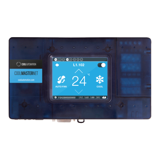
CloudBox installation complete CloudBox Unit screen After successful installation, unit’s screen will show all the detected indoor units and their statuses. Active HVAC line (DK 9/10) (Groups/Units) Inactive HVAC line All ON/OFF operation button Scrollbar Connected indoor unit with it’s address and Set-Point temperature indication. -
Page 21: How To Change The Brand Of A Specific Line
How to change the brand of a specific line In order to change the HVAC brand type on a specific line, please follow the below procedure on CoolMasterNet screen: Go to Settings (gearbox in a left upper corner) Configure the HVAC line type (Ex. L1) Go to HVAC Line Make sure the DIP switches are set properly for the brand (according to the details in the brand relevant section above) -
Page 22: Connect To Coolautomation Cloud Apps
Connection to the CoolRemote Cloud using local network Cloud Apps... - Page 23 Connection to the CoolRemote Cloud using 3G/4G router Cloud Apps 3G/4G router can be supplied separately by Coolautomation or purchased locally. Local Data SIM card is required.
-
Page 24: Power Supply
Power Supply Option A Option B AC Power supply adapter Direct DC power supply (Included in the Box) -
Page 25: Mounting On Din Rail
Mounting on a DIN rail... -
Page 26: Mounting On A Wall
Mounting on a wall... -
Page 27: Online Documentation And Support
Online Documentation and Support Scan the QR code (on the box or back of the device) to get to: Online Documentation Registration to the CoolAutomation Cloud Apps Support 24°... - Page 28 Need more help? Visit us at: https://coolautomation.com/support/#products...
Need help?
Do you have a question about the CLOUDBOX and is the answer not in the manual?
Questions and answers