
Related Manuals for CoolAutomation CoolMaster


Summary of Contents for CoolAutomation CoolMaster
- Page 1 Quick Installation Guide CoolMaster Product Line: CoolMaster, CoolMasterPro, CoolMasterNet HVAC Bridge Version 3.9.4...
-
Page 2: Warning
Any lack of electric circuit or any deficiency caused by installation may result in an electric shock or fire. • Do not relocate or reinstall the CoolMaster device by yourself. • Any deficiency caused by your own re-installation may result in an electric shock or fire. -
Page 3: Caution
CAUTION • Do not allow children to play with the CoolMaster device and supervise them not to get access to the appliance. • CoolMaster device is not to be used by persons with reduced physical, sensory or mental capabilities, or lack of experience and knowledge. - Page 4 Operating the CoolMaster device in such conditions can cause a fire. High temperature area or directly flamed point. Heating and/or fire can occur. Moist area, where there is exposure to water. If water enters the inside of the CoolMaster device, it may cause electric shock and electrical components may fail.
-
Page 5: Table Of Contents
HVAC Mitsubishi Electric Non-VRF HVAC Panasonic/Sanyo VRF How to change the brand of a specific line HVAC Toshiba VRF (Carrier) CoolMaster Device installation complete HVAC Hitachi VRF (Hisense, York, JCI) Home Automation, BMS & CoolRemote App HVAC Haier VRF (York, Trane, CIAC) -
Page 6: What's In The Box
What’s in the box AC Power supply adapter CoolMaster device 100V-240V 50/60hz to 12V Optional 1 RS232 DB9 1 USB-Mini USB 1 Ethernet Male to Female cable cable cable... -
Page 7: Coolmaster Device
CoolMaster device (option) -
Page 8: Preconfigured Coolmaster Device
Preconfigured CoolMaster Device Type label Type label with Configuration sticker This label uniquely identifies the manufacturer’s configuration of A preconfigured label example: the CoolMaster device. Located on the back of the enclosure. configured for LG on L7... -
Page 9: Hvac Line Configuration
HVAC Line configuration... -
Page 10: Hvac Daikin Vrv (Yanmar)
Connecting to the line plug Secure the cables in the L1 line plug. Plugging to the CoolMaster device Insert the plug in to the CoolMaster device L1 socket. Check DIP Switches are set correctly Dip switches setup for VRV HVAC system on L1. -
Page 11: Hvac Daikin Non-Vrv
, while DC voltage is present on L1, may damage thr CoolMaster device. device MAke sure CoolMaster device is disconnected from power and HVAC line. HVAC Communication Terminals HVAC Indoor connection * Polarity is not required on the HVAC communication line. -
Page 12: Hvac Mitsubishi Electric Vrf (Trane)
Connecting to the line plug Secure the cables in the L1 line plug. Plugging to the CoolMaster device Insert the plug in to the CoolMaster device L1 socket. Check DIP Switches are set correctly Dip switches setup for VRF HVAC system on L1. -
Page 13: Hvac Mitsubishi Electric Non-Vrf
, while DC voltage is present on L1, may damage thr CoolMaster device. device MAke sure CoolMaster device is disconnected from power and HVAC line. HVAC Communication Terminals HVAC Indoor connection * Polarity is not required on the HVAC communication line. -
Page 14: Hvac Panasonic/Sanyo Vrf
Connecting to the line plug Secure the cables in the L1 line plug. Plugging to the CoolMaster device Insert the plug in to the CoolMaster device L1 socket. Check DIP Switches are set correctly Dip switches setup for VRF HVAC system on L1. -
Page 15: Hvac Toshiba Vrf (Carrier)
Connecting to the line plug Secure the cables in the L1 line plug. Plugging to the CoolMaster device Insert the plug in to the CoolMaster device L1 socket. Check DIP Switches are set correctly Dip switches setup for VRF HVAC system on L1. -
Page 16: Hvac Hitachi Vrf (Hisense, York, Jci)
Connecting to the line plug Secure the cables in the L1 line plug. Plugging to the CoolMaster device Insert the plug in to the CoolMaster device L1 socket. Check DIP Switches are set correctly Dip switches setup for VRF HVAC system on L1. -
Page 17: Hvac Haier Vrf (York, Trane, Ciac)
Connecting to the line plug Secure the cables in the L1 line plug. Plugging to the CoolMaster device Insert the plug in to the CoolMaster device L1 socket. Check DIP Switches are set correctly Dip switches setup for VRF HVAC system on L1. -
Page 18: Hvac Mitsubishi Heavy Vrf
Connecting to the line plug Secure the cables in the L7 line plug. Plugging to the CoolMaster device Insert the plug in to the CoolMaster device L7 socket. Check DIP Switches are set correctly Dip switches setup for VRF HVAC system on L7. -
Page 19: Hvac Lg Vrf (Arcelik)
Connecting to the line plug Secure the cables in the L7 line plug. Plugging to the CoolMaster device Insert the plug in to the CoolMaster device L7 socket. Check DIP Switches are set correctly Dip switches setup for VRF HVAC system on L7. -
Page 20: Hvac Aux Vrf (Rheem, Igc)
Connecting to the line plug Secure the cables in the L7 line plug. Plugging to the CoolMaster device Insert the plug in to the CoolMaster device L7 socket. Check DIP Switches are set correctly Dip switches setup for VRF HVAC system on L7. -
Page 21: Hvac Gree/Gmv4 Vrf (Lennox, Tica, Innovair)
Connecting to the line plug Secure the cables in the L7 line plug. Plugging to the CoolMaster device Insert the plug in to the CoolMaster device L7 socket. Check DIP Switches are set correctly Dip switches setup for VRF HVAC system on L7. -
Page 22: Hvac Midea Vrf
Connecting to the line plug Secure the cables in the L7 line plug. Plugging to the CoolMaster device Insert the plug in to the CoolMaster device L7 socket. Check DIP Switches are set correctly Dip switches setup for VRF HVAC system on L7. -
Page 23: Hvac Samsung Vrf (Trane)
Connecting to the line plug Secure the cables in the L7 line plug. Plugging to the CoolMaster device Insert the plug in to the CoolMaster device L7 socket. Check DIP Switches are set correctly Dip switches setup for VRF HVAC system on L7. -
Page 24: Hvac Chigo Vrf (Rheem, Sharp)
Connecting to the line plug Secure the cables in the L7 line plug. Plugging to the CoolMaster device Insert the plug in to the CoolMaster device L7 socket. Check DIP Switches are set correctly Dip switches setup for VRF HVAC system on L7. -
Page 25: Hvac Blue Star Vrf
Connecting to the line plug Secure the cables in the L7 line plug. Plugging to the CoolMaster device Insert the plug in to the CoolMaster device L7 socket. Check DIP Switches are set correctly Dip switches setup for VRF HVAC system on L7. -
Page 26: Hvac Tica Vrf
Secure wire in the A2 & B2 terminals on the Outdoor Unit. Connect to CoolMaster device Secure wire from Outdoor unit to the wire plug. Wire Plug Insert wire plug to CoolMaster device L7 socket. Check DIP Switches are set correctly Dip switches setup for VRF HVAC system on L7. -
Page 27: Hvac Gree Gmv5, Gmv6 (Gree) Vrf
This adapter includes a CAN bus 120 Ω resistor. Plugging to the CoolMaster device Insert the plug in to the CoolMaster device L8 (USB). Check DIP Switches are set correctly Dip switches setup for GMV5/6 VRF HVAC system on L8. -
Page 28: Hvac Fujitsu Vrf (Rheem, Atlantic)
Connecting to the Echelon adapter Echelon U10 USB Network Interface (TP/FT-10) adapter is required for connecting to Fujitsu VRF. (Not supplied by CoolAutomation) Connect Echelon via USB Extension cable Connect the USB Extension cable (A-Male to A-Female) to the Echelon adapter. -
Page 29: How To Change The Brand Of A Specific Line
How to change the brand of a specific line In order to change the HVAC brand type on a specific line, please follow the below procedure on CoolMaster device screen: Go to Settings Configure the HVAC line type Go to HVAC Line... -
Page 30: Coolmaster Device Installation Complete
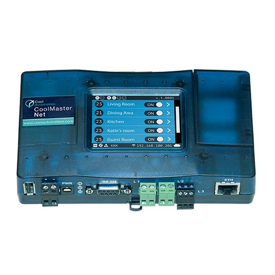
CoolMaster device installation complete CoolMaster device Unit screen After successful installation, unit’s screen will show all the detected indoor units and their statuses. Active HVAC line (DK 9/10) (Groups/Units) Inactive HVAC line All ON/OFF operation button Scrollbar Connected indoor unit with it’s address and Set-Point temperature indication. -
Page 31: Home Automation, Bms & Coolremote App
Home Automation, BMS & CoolRemote App... -
Page 32: Power Supply
Power Supply Option A Option B AC Power supply adapter Direct DC power supply (Included in the Box) -
Page 33: All On/Off Operation By External Signal
All On/Off operation by external signal All On All Off... -
Page 34: Mounting On Din Rail
Mounting on a DIN rail... -
Page 35: Mounting On A Wall
Mounting on a wall... -
Page 36: Online Documentation And Support
Online Documentation and Support Scan the QR code (on the box or back of the device) to get to Online Documentation Registration to the CoolRemote App Support 24°... - Page 37 Need more help? Visit us at: https://coolautomation.com/support...
Need help?
Do you have a question about the CoolMaster and is the answer not in the manual?
Questions and answers