
Related Manuals for HEIDENHAIN ND 2100G


Summary of Contents for HEIDENHAIN ND 2100G
- Page 1 ND 2100G Gage-Chek Operating Instructions SALES & SERVICE: A Tech Authority, Inc. 13745 Stockton Ave. Chino CA 91710 909-614-4522 sales@atechauthority.com English (en) 11/2014...
-
Page 2: Table Of Contents
Contents Contents About these instructions..............7 Information on the model................. 7 Notes on reading the documentation............8 Storage and distribution of the documentation........8 Target group for the instructions.............. 9 Explanation of symbols................9 Safety....................10 Bestimmungsgemäße Verwendung............10 Improper use..................... 10 Personnel qualification................10 Obligations of the operating company.......... - Page 3 Contents Commissioning................51 Setting the language................52 Entering the password................53 Defining a test part.................. 54 Configuring a measuring device............. 55 Setting the date, time, date format and time format......57 Setting the display format and display resolution........ 58 Software setup................60 Setup menu....................61 7 .1.1 Accessing the Setup menu and screens........62...
- Page 4 Contents 7 .25.3 Assigning hot key functions............. 128 7.26 Setting date and time: Clock..............134 7.27 Setting parameters for displays, keys and audio output: Misc..136 7.28 Locking or unlocking critical functions: Supervisor......139 Custom programming..............142 Introduction to formulas................ 142 8.1.1 How do formulas relate inputs to dimensions?......143 8.1.2...
- Page 5 Contents values: dmn and dmx............... 180 8.5.13 Determining the average and median of dynamically sampled values: davg and dmd.............. 182 8.5.14 Evaluating the pass/fail status: fail........... 183 xtra menu functions................184 8.6.1 Creating user prompts: Ask............. 186 8.6.2 Generating audio alert: Beep............187 8.6.3 Clearing data for all parts: ClrAllD..........
- Page 6 Contents Measurement, review, output of results........230 Selecting the part................... 231 Establishing a measurement reference (calibrating)......232 9.2.1 Calibration groups (G1, G2, G3...G18)........233 9.2.2 Calibration of transducer resolution (Min-Max calibration)..234 9.2.3 Establishing a temporary dimension reference (preset)... 236 Conducting measurements..............240 Reviewing measurements..............
-
Page 7: About These Instructions
The documentation is valid if the document number matches the document number given under www.heidenhain.de. For this purpose, you need to compare the product designation, the ID number and the index given on the ID label with the corresponding details... -
Page 8: Notes On Reading The Documentation
About these instructions Storage and distribution of the documentation Notes on reading the documentation The table below lists the components of the documentation in the order of priority for reading. WARNING Failure to comply with the documentation may result in fatal accidents, personal injury or damage to equipment. -
Page 9: Target Group For The Instructions
About these instructions Explanation of symbols Target group for the instructions The Operating Instructions must be read and observed by every person who performs any of the following tasks: Mounting Installation Commissioning Setup, programming and operation Cleaning and maintenance Troubleshooting Removal Disposal Explanation of symbols... -
Page 10: Safety
Eine andere oder darüber hinausgehende Benutzung des Geräts gilt als nicht bestimmungsgemäß und kann zu Gefahren und Schäden führen. Das Gerät unterstützt die Verwendung einer Vielzahl von Peripheriegeräten verschiedener Hersteller. HEIDENHAIN kann keine Aussagen zur bestimmungsgemäßen Verwendung dieser Geräte treffen. Die Informationen zur bestimmungsgemäßen Verwendung aus den entsprechenden Dokumentationen müssen beachtet werden. -
Page 11: Obligations Of The Operating Company
General safety precautions The product supports the use of a wide variety of peripheral devices from different manufacturers. HEIDENHAIN cannot make any statements on the specific safety precautions to be taken for these devices. The safety precautions provided in the respective documentations must be observed. - Page 12 Safety General safety precautions WARNING Warns of potential danger. Failure to avoid the danger may result in severe injury or death. CAUTION Warns of potential danger. Failure to avoid the danger may result in slight or minor injury. NOTICE Warns of a potentially harmful situation. Failure to avoid the situation may cause damage to the product or to equipment in its surroundings.
-
Page 13: Electrical Safety Precautions
Safety General safety precautions 2.5.2 Electrical safety precautions DANGER When opening the product, there is a possibility of coming into contact with live electrical components. This may result in electric shock, burns or death. In addition, opening the product will invalidate the guarantee, warranty and liability of the manufacturer for any resulting accidents, personal injury or equipment damage. -
Page 14: Mounting
Check the delivery for completeness. Check the delivery for damage. If any components were damaged in transit, keep the packaging materials for inspection and contact your HEIDENHAIN distributor or OEM. This applies also if you need replacement parts. In case of damage in Have the shipping agent confirm the damage. -
Page 15: Assembly
Mounting Assembly The following items are optionally available and can be ordered from HEIDENHAIN as Accessories additional accessories: Optional accessories ID number Mounting adapter 682419-01 Mounting stand 382892-02 Foot switch 681041-01 Remote keypad 681043-01 QUADRA-CHEK Wedge communication software 709141-01 Protective cover... - Page 16 Mounting Assembly Mounting the unit with mounting stand on a benchtop or machine (optional) Using the mounting holes provided on the underside of the mounting stand, you can firmly screw the unit to a benchtop. Horizontal tilting of the unit in the tilt guides is still possible after screw-mounting. If the unit has a pre-installed mounting adapter, you need to remove the mounting adapter first and then attach the mounting stand.
- Page 17 Mounting Assembly Mounting the unit with mounting adapter on a support arm or benchtop Using the mounting holes on the underside of the pre-installed mounting adapter, you can screw the unit to a support arm or benchtop. Dimensions of mounting adapter M6,3 - 1.3 x 16.5 (1/4 - 20“...
-
Page 18: Installation
Installation Installation NOTICE Disturbances caused by lack of grounding or improper grounding! Never operate the unit without proper ground connection. Connect the ground connector on the rear panel to the central grounding point of the unit. Minimum cross section of the conductor: 6 mm NOTICE Risk of damage to internal components! Do not engage or disengage any connecting elements while the unit is under... -
Page 19: Product Overview
Installation Product overview Product overview Rear panel Power switch Relay outputs I/O interface RS-232-C/V.24 port Inputs for measuring devices Power connector Line fuse The number and type of measuring device connectors may vary from unit to unit. - Page 20 Installation Product overview Left side panel The left side panel (as seen from the front) provides the following connectors: Speaker/headphone jack USB Type A connector RJ-45 jack for foot switch or remote keypad...
-
Page 21: Connecting Power
Installation Electrostatic discharge Connecting power WARNING Risk of electric shock! Improper grounding of electrical devices involves a risk of serious injury or death by electric shock. Always use 3-wire power cables. Make sure the ground wire is correctly connected to the ground of the building's electrical installations. -
Page 22: Connecting Measuring Devices
Installation Connecting measuring devices Connecting measuring devices Measuring devices are connected to the channel inputs provided on the rear panel. For Connection information about their location on the rear panel, see "Rear panel", page 19. possibilities The number and type of connectors available for the measuring devices may vary from unit to unit. -
Page 23: Connecting A Computer
Installation Connecting a computer For TTL pin layouts 9-pin D-sub connector: Pin layout Connecting a computer Connect a computer COM port to the unit's RS-232/V.24 serial port using a standard serial cable. For information about the port's location on the rear panel, see "Product overview", page 19. -
Page 24: Connecting Headphones And Usb Printer
A list of supported printers is available as a document from www.heidenhain.de. Connect the USB printer to the USB Type A port on the side of the housing. Make sure the USB cable plug is fully inserted. For information on the location of the USB port, see "Rear panel", page 19. -
Page 25: Connecting A Foot Switch And Remote Keypad (Optional Accessories)
Installation Connecting a foot switch and remote keypad (optional accessories) Connecting a foot switch and remote keypad (optional accessories) The foot switch and the remote keypad are available as optional accessories. For more information see "Items supplied", page 14. The connecting cable fixed to the foot switch has an RJ-45 plug for connection to the Connecting the foot RJ-45 jack on the left side of the unit. -
Page 26: Wiring Of Switching Inputs And Outputs
Installation Wiring of switching inputs and outputs RJ-45 plug: Pin layout Case S-1, S-2 COM: Common Wiring of switching inputs and outputs The functions are based on the formulas and values stored by qualified personnel. The wiring of the switching inputs and outputs depends on the customer's peripherals (see manufacturer's documentation). - Page 27 Installation Wiring of switching inputs and outputs Relay connector: Pin layout COM: Common NC: Normally closed NO: Normally open The I/O interface enables the digital readout unit to communicate with the peripherals Data I/O interface through TTL inputs and outputs. Signals from peripherals can be evaluated and connected peripheral devices can be controlled.
-
Page 28: Basic Operation
Basic Operation Basic Operation Operation of the unit is performed using various keys when conducting measurements. The LCD screen displays different menus for creating formulas and making additional settings. The measurement results can be displayed in different views on the screen. Measurements are conducted under user control, or are semi-automated and conducted in conjunction with a multipoint inspection system. -
Page 29: Product Overview
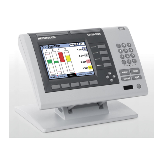
Basic Operation Product overview Product overview Front panel enter finish quit cancel Fast track keys Dimension keys «Send» key Numerical keys «LCD on/off» key Command keys Arrow keys Soft keys LCD screen The front panel provides the LCD screen and the operating keys, see "LCD screen", page 30 and "Keys", page 32. -
Page 30: Lcd Screen
Basic Operation Product overview 5.1.1 LCD screen Screen layout Views, measured value displays and menus Functions of the dimension keys, change depending on situational context Functions of the soft keys, change depending on situational context Depending on the selected function, the current dimension values and measurement results can be represented in different ways. - Page 31 Basic Operation Product overview Left: Vertical bar graph Right: Dial display Left: Line graph Right: Histogram Left: Measurement data Right: SPC data...
-
Page 32: Keys
Basic Operation Product overview 5.1.2 Keys Fast track keys Function Function programmed for the left key. Default: «RsetDyn» For information on the assignment of hot keys, see "Configuring hot keys: Hot Keys", page 127. Function programmed for the right key. Default: «enter»... - Page 33 Basic Operation Product overview Command keys Function Enter data: Enter data for a measurement. The displayed information is stored as mea- surement or configuration data. This information includes current dimension values or al- enter phanumeric data for a configuration or user prompt data field. Exit a screen: Exit the current screen and save any changes that were made.
-
Page 34: Switch-On / Switch-Off
Basic Operation Switch-on / Switch-off Switch-on / Switch-off For information on the location of the power switch, see "Rear panel", page 19. Switch-on Turn the power switch on. After switching the power on, or after a power failure, the startup screen will be displayed. -
Page 35: Dro View
Basic Operation DRO view DRO view The DRO view is the default home screen. It provides numeric displays of the current DRO view values of up to four dimensions. The symbols in the upper right corner of the screen indicate: Unit of measure Current datum Number or name of the current part... -
Page 36: View Function
Basic Operation DRO view The soft-key row in the DRO view provides the following functions: Functions in the DRO view «View» function, see "View function", page 36 «in/mm» function, see "in/mm function", page 44 «Master» function, see "Master function", page 44 «Menu»... - Page 37 Basic Operation DRO view The following information is provided on the upper left of the LCD screen: Time and date that the individual value was stored Sample ID number for the dimension and the associated data value Nominal and limit values (only if a single dimension is displayed) To toggle between a single and multiple line graphs displayed on the screen: Press the «Graph...»...
- Page 38 Basic Operation DRO view To display the dimensions in a histogram: «Histo...» Press the «Histo...» soft key. This view displays the values for up to 16 dimensions as histograms. To toggle between a single and multiple histograms displayed on the screen: Press the «Histo...»...
- Page 39 Basic Operation DRO view To display the dimensions in a bar or dial display: «Bar...» Press the «Bar...» soft key. The bar and dial views provide graphic displays of the current values of up to 16 dimensions. The default setting for the Bar view can be configured to display the bars in horizontal or vertical orientation.
- Page 40 Basic Operation DRO view To display the dimensions in a data table: «Data...» Press the «Data...» soft key. The Data view displays tables containing measurement data stored for up to 4 dimensions. To toggle between the display of data for all dimensions and data for a single dimension that includes SPC statistics: Press the «Data...»...
- Page 41 Basic Operation DRO view To display xcharts for the dimensions: x charts Press the «x» soft key. This view is displayed for the dimensions in place of the line graph discussed earlier. It graphs the mean (x) of each subgroup for up to 16 dimensions. The following information is provided on the upper left of the LCD screen: Time and date that the individual value was stored Sample ID number for the dimension and the associated data value...
- Page 42 Basic Operation DRO view To display r charts for the dimensions: r charts Press the «r...» soft key. This view graphs the range (r) of each subgroup for up to 16 dimensions. The range is not recalculated for each measurement, but each time a subgroup is completed, see "Defining statistical parameters: SPC", page 82.
- Page 43 Basic Operation DRO view To display the dimensions in a data table: «Data...»: Dimension data tables Press the «Data...» soft key. This view displays tables containing measurement data for up to 4 dimensions. The Data view is slightly different from that for SPC subgroups of one. Individual subgroups are indicated by a horizontal line in tables for single dimensions.
-
Page 44: In/Mm Function
Basic Operation DRO view 5.3.2 «in/mm» function Pressing this soft key toggles the display between inch and millimeter units of measure. This function for toggling the units of measure has no influence on the measurement configuration of the input channels in the «Channels» setup screen. -
Page 45: Menu Screen
Basic Operation Menu screen Menu screen In the DRO screen, press the «Menu» soft key. Opening the «Menu» screen The soft-key row changes to allow choosing between different menus. In the Menu screen, the soft-key row provides the following functions: «View»... -
Page 46: Extra Function
Basic Operation Menu screen To zero a specific or all incremental datums: Zeroing incremental datums Press the «Zero...» soft key. Press the «Zero» soft key for the datum(s) to be zeroed. For more information see "Zeroing a dimension reference", page 236. Setting incremental Press the «Preset»... - Page 47 Basic Operation Menu screen The soft-key row provides the following options: Options DMS/DD: Toggles the display of angles between Degrees, Minutes, Seconds (DMS) and Decimal Degrees (DD) Recall: Applies the last used incremental datum (D1) that was preset by the user Rad/Dia: Toggles between the radius and diameter measurement types on the DRO screen, if radius or diameter was specified in the «Formats»...
- Page 48 Basic Operation Menu screen For the duration of the Fast3 function process, the unit adopts an X/Y axis reference Example of Fast3 : system. Channel 1 is referred to as the X axis, and channel 2 as the Y axis. User-specified limits exceeded Y axis (C2)
-
Page 49: Setup Function
Basic Operation Menu screen Activating the Fast3 Press the «Menu/Extra» soft keys. function Use the arrow keys to highlight the Fast3 function. Press «enter». Entering parameters Enter a Y axis (channel 2) upper limit. Enter a Y axis (channel 2) lower limit. Enter an X axis (channel 1) capture increment. -
Page 50: Menu Tree
Basic Operation Menu tree Menu tree View... in/mm Menu View... in/mm Datum... Extra Setup View... in/mm Datum... Extra Setup «Extra» «Setup» menu: menu: GMS/DD About D0/D1 Zero Preset Clear Recall Dimensions Rad/Dia Formats RsetDyn Formulas Send Variables SendRec Tolerances Zero All Zero A Zero B Zero C... -
Page 51: Commissioning
Commissioning Commissioning Personnel requirement The following steps are only to be performed by qualified personnel! For more information see "Personnel qualification", page 10. The following essential commissioning steps are required to provide a basic Essential configuration. They are the first settings to be made after installation: commissioning steps Chap. -
Page 52: Setting The Language
Commissioning Setting the language Setting the language Chap. 6.1: Chap. 6.2: Chap. 6.3: Chap. 6.4: Chap. 6.5: Chap. 6.6: Setting the lan- Entering the Defining a test Configuring Setting the date, Setting the dis- guage password part a measuring time, date for- play format and device mat and time... -
Page 53: Entering The Password
Commissioning Entering the password Entering the password Chap. 6.1: Chap. 6.2: Chap. 6.3: Chap. 6.4: Chap. 6.5: Chap. 6.6: Setting the Entering Defining a Configuring Setting the Setting the language the pass- test part a measur- date, time, display for- word ing device date format... -
Page 54: Defining A Test Part
Commissioning Defining a test part Defining a test part Chap. 6.1: Chap. 6.2: Chap. 6.3: Chap. 6.4: Chap. 6.5: Chap. 6.6: Setting the Entering Defining a Configuring Setting the Setting the language the pass- test part a measur- date, time, display for- word ing device... -
Page 55: Configuring A Measuring Device
Commissioning Configuring a measuring device Configuring a measuring device Chap. 6.1: Chap. 6.2: Chap. 6.3: Chap. 6.4: Chap. 6.5: Chap. 6.6: Setting the Entering Defining a Configuring Setting the Setting the language the pass- test part a measur- date, time, display for- word ing device... - Page 56 Acu-Rite type (coded like ENC 150 or SENC 150) Abs HH The connected measuring device has distance-coded reference marks of the HEIDENHAIN type with a nominal increment of 1000 signal peri- Abs HH2 The connected measuring device has distance-coded reference marks...
-
Page 57: Setting The Date, Time, Date Format And Time Format
Commissioning Setting the date, time, date format and time format Press the arrow key to select the reference mark type and confirm your selection with «enter». The Ref Marks field and the list of reference mark types are not available for EnDat encoders! Select C1 with the arrow keys and press the «+»... -
Page 58: Setting The Display Format And Display Resolution
Commissioning Setting the display format and display resolution Soft key Date format display (example) «M.D.YY:» 09.20.13 «D.M.YY:» 20.09.13 Press «enter». The highlight moves to the Time Format field. The Time Format field specifies the format of the time shown on the LCD and printed Setting the time on reports. - Page 59 Commissioning Setting the display format and display resolution Selecting a dimension Press the «right» arrow key. Dimension is highlighted. Press the «down» arrow key press the «Dec/Inc» soft key to highlight the desired dimension and press «enter» to confirm. Radius or diameter measurements can be specified for cylindrical and spherical parts Specifying radius or or parts with curved surfaces.
-
Page 60: Software Setup
Software setup Software setup Personnel requirement The following steps are only to be performed by qualified personnel! For more information see "Personnel qualification", page 10. Overview This chapter contains a complete description of all the setup parameters for the unit. It is designed as a reference guide. -
Page 61: Setup Menu
Software setup «Setup» menu «Setup» menu Most operating parameters are configured using screens and data fields accessed from the «Setup» menu. Highlighting «Setup» menu items on the left side of the screen displays the corresponding parameter data fields and choice fields on the right side of the screen. -
Page 62: Accessing The Setup Menu And Screens
Software setup «Setup» menu 7.1.1 Accessing the «Setup» menu and screens Accessing the Press the «Menu» soft key. «Setup» menu Press the «Setup» soft key. The «Setup» menu is displayed and shows the first setup screen: Accessing the Use the «up» and «down» arrow keys to scroll through the «Setup» menu and «Setup»... -
Page 63: Leaving The Setup Menu
Software setup «Setup» menu The functions of the dimension keys change to speed up setup screen navigation when Using dimension keys the «Setup» menu is displayed. Dimension keys can be used to move to the top or in the «Setup» mode bottom of the «Setup»... - Page 64 Software setup «Setup» menu Entering parameters Highlight a setup parameter. Available options are displayed in the soft-key row at the bottom of the screen. Press the desired soft key. The selected option is entered into parameter field. Copying parameters to other parts, dimensions or channels A single highlighted parameter or all parameters of the current part, dimension or If parameters differ...
- Page 65 Software setup «Setup» menu Saving a parameter and advancing to the next To save the entered parameter value and advance to the next parameter field: Press «enter». Saving a parameter and returning to the «Setup» menu To return to the «Setup» menu: Press «finish».
-
Page 66: Deleting Data Entries
Software setup «Setup» menu 7.1.4 Deleting data entries Highlight a data field. Press «cancel» to erase the rightmost character. 7.1.5 Saving or loading configurations Insert a USB drive into the USB port. Navigate to the «Supervisor» setup screen. Highlight the Password field and enter the password if necessary. Press the «SaveX»... -
Page 67: Selecting The Language: About
Software setup Defining part and dimension labels: «Dimensions» Selecting the language: «About» «Menu/Setup» soft keys Activation The «About» setup screen contains selections for changing the language of text Short description displayed on the LCD, included in transmitted data and printed on reports. Software and hardware version information and the number of input channels are displayed on the bottom of the screen. - Page 68 Software setup Defining part and dimension labels: «Dimensions» Structure and format of parts Part numbers consist of two numeric digits in the range from 0 to 99 assigned by the system in sequence as new parts are added. Part names consist of up to 8 alphanumeric characters entered from the Alpha Entry screen and the numeric keypad.
- Page 69 Software setup Defining part and dimension labels: «Dimensions» Labeling parts and dimensions Part labels contain up to 8 alphanumeric characters. Dimension labels contain up to 3 alphanumeric characters. Alphabetic characters are in the range from A to Z and can be upper or lower case.
-
Page 70: Specifying The Display Format And Display Resolution: Formats
Software setup Specifying the display format and display resolution: «Formats» Copying dimension parameters to other parts Dimensions assigned to one part can be copied to another to save setup time when similar or identical measurements must be performed on new parts. The labels, formulas and all other parameters will be copied to the next new part. - Page 71 Software setup Specifying the display format and display resolution: «Formats» Specifying radius or diameter Radius or diameter measurements can be specified for cylindrical and spherical parts or parts with curved surfaces. When radius or diameter measurements are specified, the corresponding symbol will be displayed near the associated dimension on the DRO screen.
-
Page 72: Creating Formulas: Formulas
Software setup Creating formulas: «Formulas» Creating formulas: «Formulas» «Menu/Setup» soft keys, «Formulas» setup screen Activation When conducting measurements, formulas are used to define and display dimensions Short description based on the channel inputs from the measuring devices. These formulas are constructed by the user to display: One dimension based on one channel, e.g. -
Page 73: Defining Variables: Variables
Software setup Defining variables: «Variables» Defining variables: «Variables» «Menu/Setup» soft keys, «Variables» setup screen Activation Formulas use variables as symbols or names that represent values. Short description For example, in the expression: C1+Var1() Var1() is a variable, its value is flexible and is determined by operations on a different formula line for the current part. -
Page 74: Defining Tolerance Values: Tolerances
Software setup Defining tolerance values: « Tolerances» Defining tolerance values: «Tolerances» This section describes the following functions: Overview Nominal values with tolerances Nominal with +/- tolerances Nominal with ++ tolerances Nominal with -- tolerances Nominal with fixed limits Specifying an audio alert Mirroring values «Menu/Setup»... - Page 75 Software setup Defining tolerance values: « Tolerances» The defined pass, warning and fail levels are shown next to the bar graph. They have the following meanings: Tolerances Description Pass Above low warning and below high warning. Pass values fall within the specified range of acceptable values. Warning Within the range of acceptable values, but close to the fail level.
- Page 76 Software setup Defining tolerance values: « Tolerances» Highlight the Dimension field. Specifying a nominal value with +/- Press the «+/-» soft key to specify a nominal value with +/- tolerances. tolerances Highlight the desired tolerance field. Enter the desired tolerance value. Press «enter».
- Page 77 Software setup Defining tolerance values: « Tolerances» Nominal with ++ tolerances A nominal value is displayed with tolerances entirely on the plus side of the nominal value. 0.080 Nom + Max 0.060 Nom + Limit 0.050 Nom + Warning 0.030 Nom + Warning 0.020 Nom + Limit 0.000 Nom + Min 3.000 mm nominal...
- Page 78 Software setup Defining tolerance values: « Tolerances» Nominal with -- tolerances A nominal value is displayed with tolerances entirely on the minus side of the nominal value. 3.000 mm nominal -0.010 Nom - Max -0.020 Nom - Limit -0.030 Nom - Warning -0.050 Nom - Warning -0.060 Nom - Limit -0.070 Nom - Min...
- Page 79 Software setup Defining tolerance values: « Tolerances» Nominal with fixed limits A nominal value is displayed between plus and minus fixed limits. Specifying fixed limits Press the «Limits» soft key. above and below a Highlight the desired tolerance field. nominal value Enter the desired tolerance value.
- Page 80 Software setup Defining tolerance values: « Tolerances» Specifying an audio alert Audio alerts can be specified that sound when a dimension reaches warning and limit values. The audio alert sounds when a warning or limit threshold is crossed, and will not sound again until the alert is reset by crossing the threshold again in the opposite direction.
- Page 81 Software setup Defining tolerance values: « Tolerances» Mirroring values Positive and negative Max, Min and Warn values can be set automatically depending on the Nom + Limit value. The limits will also be entered into the «SPC» setup screen. New values will be: - Limit = + Limit Max, Min = + Limit + 5 % Warn = SPC Warning Per.
-
Page 82: Defining Statistical Parameters: Spc
Software setup Defining statistical parameters: «SPC» Defining statistical parameters: «SPC» This section describes the following functions: Overview Subgroup Size Max Subgroups Graph Pts Next Record ID Dimension UCL and LCL x Ucl, x Lcl, r Ucl and r Lcl UCL and LCL Recalculating x Ucl and x Lcl r Ucl and r Lcl Recalculating r Ucl and r Lcl... - Page 83 Software setup Defining statistical parameters: «SPC» The differences between subgroups of 1 and subgroups greater than 1 are described in detail later in this «SPC» section. Max Subgroups The Max Subgroups parameter specifies the maximum number of subgroups to be stored for the specified dimension.
- Page 84 Software setup Defining statistical parameters: «SPC» Dimension Highlight the Dimension field. Specifying the dimension used Press the «Dec» or «Inc» soft key until the desired dimension is displayed in the for the current SPC field. settings Press «enter». UCL and LCL The UCL and LCL fields are displayed when the subgroup size is 1.
- Page 85 Software setup Defining statistical parameters: «SPC» Manually specifying r Highlight the r Ucl or r Lcl field. Ucl and r Lcl Use the numeric keypad to enter the desired r Ucl or r Lcl. Press «enter». r Ucl and r Lcl recalculation Once subgroup data has been collected, the upper and lower control limits can be simultaneously recalculated.
-
Page 86: Creating Header Labels And User Prompts: Header
Software setup Allocating and using memory: «Memory» Creating header labels and user prompts: «Header» «Menu/Setup» soft keys, «Header» setup screen Activation The «Header» setup screen contains fields for creating header labels and user prompts Short description for text that will be included on printed reports. Header information is printed in text fields at the top of all reports and is arranged as shown on the «Header»... -
Page 87: Labeling System Dimension Formulas: S Labels
Software setup Labeling system dimension formulas: «S Labels» Memory allocations are changed by the system when the user changes: The number of parts The number of measurements performed Formula complexity Parameters in the «SPC» setup screen The «Memory» setup screen is provided only as a convenience for determining the system's memory usage. -
Page 88: Creating System Formulas: S Formulas
Software setup Creating system formulas: «S Formulas» 7.12 Creating system formulas: «S Formulas» «Menu/Setup» soft keys, «S Formulas» setup screen Activation The «S Formulas» setup screen is used for constructing system formulas. System Short description dimensions are created in system formulas, which are used in the same way as dimension formulas (see "Labeling system dimension formulas: S Labels", page 87). -
Page 89: Displaying The States Of Global Variables: Globals
Software setup Configuring measuring devices: «Channels» 7.13 Displaying the states of global variables: «Globals» «Menu/Setup» soft keys, «Globals» setup screen Activation The «Globals»setup screen shows the current state of global variables and is used like Short description the «Variables» setup screen discussed earlier in this chapter. Global variables are used like variables except that, unlike variables, globals can be used by any part. - Page 90 Software setup Configuring measuring devices: «Channels» Selecting the input channel type Measuring devices are connected to the channel inputs provided on the rear panel of the unit. The number and type of the measuring devices are specified when the unit is purchased, but might need to be specified again in the field.
- Page 91 Software setup Configuring measuring devices: «Channels» Highlight the Type field. Selecting the input channel type Press the «List» soft key to display the list of available input channel types. Use the «up» or «down» arrow key to select the desired input channel type. Press «enter».
- Page 92 Software setup Configuring measuring devices: «Channels» Press «enter». Balance scalars are displayed. Press the «OK» soft key to save the balance scalars. Press «enter» to move to another field Press «finish» to exit the screen. Channel 1 Channel 2 Material thickness is measured by two balanced probes. Place the reference standard between the two probes.
- Page 93 Software setup Configuring measuring devices: «Channels» Setting the resolution for the linked channels After balancing the master linked channels, the resolution of the first linked channel must be taught. The resulting resolution is applied to both linked channels. Confirm that the Master Type parameter in the «Master» setup screen is set to Teaching the resolution for the linked channels Min-Max.
- Page 94 Software setup Configuring measuring devices: «Channels» Specifying the input channel resolution The Resolution field defines the input resolution for encoders, transducers, thermocouples, RS-232/V.24 probe networks and other measuring devices. Resolution values can either be manually entered if they are known, as in the case of encoders or taught, as in the case of transducers.
- Page 95 The connected measuring device has distance-coded reference marks of the Acu-Rite type (coded like ENC 150 or SENC 150) Abs HH The connected measuring device has distance-coded reference marks of the HEIDENHAIN type with a nominal increment of 1000 signal peri-...
- Page 96 Ref Marks Description Abs HH2 The connected measuring device has distance-coded reference marks of the HEIDENHAIN type with a nominal increment of 5000 signal pe- riods Highlight the desired reference mark type. Press «enter» to confirm the selection. Press «enter» to move to the next parameter.
- Page 97 Software setup Configuring measuring devices: «Channels» Calibrating LVDT and HBT transducer gain The unit includes hardware and software for automatically calibrating the system to accommodate variations in transducer output level. Highlight the Gain field. Calibrating LVDT and HBT transducer gain Press the «Teach»...
- Page 98 Software setup Configuring measuring devices: «Channels» When the transducer gain has been calibrated and zero adjustment against the nominal reference surface has been completed, the transducer resolution can be calibrated using the «Master» function. The transducer is then ready to measure. Transducer resolution is usually calibrated periodically on a schedule determined by the application and the measurement environment.
- Page 99 Software setup Configuring measuring devices: «Channels» Specifying an RS-232/V.24 input port Multiple RS-232/V.24 serial ports are provided on units that include RS-232/V.24 input channels. In most instances the secondary port should be used as the input channel for measuring devices. However, the primary port can be specified if desired. Highlight the Uart Id field.
-
Page 100: Calibrating Encoders And Transducers: Master
Software setup Calibrating encoders and transducers: «Master» 7.15 Calibrating encoders and transducers: «Master» This section describes the following functions: Overview Specifying the number of calibration points Selecting the calibration type Locking the calibration process if warnings occur Specifying a calibration interval Using dynamic Min/Max values for calibration Setting the slew limit for warning messages Specifying Min and Max calibration warnings... - Page 101 Software setup Calibrating encoders and transducers: «Master» Locking the calibration process if warnings occur The calibration process can be locked automatically when a calibration fails and a warning is displayed. Once locked, the calibration process can only be completed by performing a new calibration that is successful or by entering the supervisor password to abort the calibration process.
- Page 102 Software setup Calibrating encoders and transducers: «Master» 2.0 cm Dmax is measured and set in Master Max 1. Setting the slew limit for warning messages High input slew rates from rapid encoder motion can result in erroneous measurements. Erroneous measurements are avoided by displaying encoder error messages when encoder values change at very high rates.
-
Page 103: Compensating Measurement Errors: Slec
Software setup Compensating measurement errors: «SLEC» When Mean calibrations are performed, only the Min Warning value is required. Specifying the acceptable range for Highlight the Min Warning field. new calibration values Enter the acceptable deviation from the original minimum master calibration value. Press «enter». - Page 104 Software setup Compensating measurement errors: «SLEC» Linear error correction (LEC) The LEC correction coefficient is created by the unit using data provided by the user in the «SLEC» setup screen. The LEC setup data provided by the user consists of the nominal and actual values of a reference standard at the two extreme ends of the measurement range.
- Page 105 Software setup Compensating measurement errors: «SLEC» At the end of the range, the nominal value is 1500 and the actual value is 1520 in this example (see figures below). This indicates a linearity error of 20 over the entire measurement range. These values are entered into Station 1. When the procedure is complete and the data has been entered, a correction coefficient is calculated for the measuring device.
- Page 106 Software setup Compensating measurement errors: «SLEC» 1000 1100 1200 1300 1400 1500 1100 1210 1520 1000 1320 1420 Machine 0,0 (Reference) Nominal (Standard) Actual (Observed) Deviation Segment 0 to Segment 6 Station 0 Stations 1 to 6 The nominal and actual values at the end of each segment are entered as data for the respective Station in the «SLEC»...
-
Page 107: Clearing All Datums
Software setup Compensating measurement errors: «SLEC» SLEC setup procedure Make sure that the resolutions and the references to the machine datum are properly configured for all measuring devices, and that any required settings using the «Master» function have been completed for the measuring devices prior to configuring the SLEC feature. -
Page 108: Power Cycling And Setting Machine Datum
Software setup Compensating measurement errors: «SLEC» 7.16.2 Power cycling and setting machine datum Chap. 7 .16.1: Chap. 7 .16.2: Chap. 7 .16.3: Chap. 7 .16.4: Chap. 7 .16.5: Chap. 7 .16.6: Clearing all Power cycling Disabling SLEC Machine zero Entering new Enabling SLEC datums and setting... -
Page 109: Machine Zero Offset
Software setup Compensating measurement errors: «SLEC» Press the «Off» soft key to disable SLEC for the selected channel. Highlight the Station field. Use the «Dec» or «Inc» soft key, if necessary,to display Station 0. If the fields for the nominal (Standard) and actual (Observed) values contain data, press the «Remove»... -
Page 110: Enabling Slec
Software setup Configuring the display: «Display» Press the «Inc» soft key to select the next station number. Highlight the Standard field. Use the numeric keypad to enter the value marked on the reference standard. Press «enter» to confirm the value. The Observed field is highlighted. - Page 111 Software setup Configuring the display: «Display» Radix for numeric displays The Radix field is used to specify the separator displayed in numeric fields. Highlight the Radix field. Specifying the separator Press the «Decimal» or «Comma» soft key. Press «enter». Display mode for angles The Current Angular field is used to specify the display mode for angles.
- Page 112 Software setup Configuring the display: «Display» Highlight the Bar Display Type field. Specifying the bar display type Press the «Bar» or «Dial» soft key. Press «enter». Colors that indicate measurement results In the Failed/Warning/Passed Color fields, different colors can be assigned to indicate the status of measurement results on DRO, Graph, Data and SPC screens.
- Page 113 Software setup Configuring the display: «Display» Units of measure Units of measure can be displayed near dimension labels on the DRO screen to increase clarity. Highlight the Show DRO Units field. Displaying units of measure on the DRO Press the «Yes» soft key. screen Press «enter».
-
Page 114: Setting The Print Format And Report Contents: Report
Software setup Setting the print format and report contents: «Report» 7.18 Setting the print format and report contents: «Report» «Menu/Setup» soft keys, «Report» setup screen Activation The «Report» setup screen contains fields for formatting and specifying the contents of Short description printed reports. - Page 115 Software setup Setting the print format and report contents: «Report» Assignment of report sections Record Number Time Stamp Dimension Labels Dimension Units Page Numbers Divider Lines Record number Two numbers are displayed below the date and time in the title bar of the Data screen. The left number is the record ID and the right number is the value of the selected dimension.
- Page 116 Software setup Setting the print format and report contents: «Report» Lines per page Horizontal divider lines and lines of text are considered lines. Highlight the Lines Per Pagefield. Specifying the lines per page Use the numeric keypad to enter the desired number of lines per report page. Press «enter».
-
Page 117: Setting Ascii Codes For Printing: Rep Chars
Software setup Setting ASCII codes for printing: «Rep Chars» 7.19 Setting ASCII codes for printing: «Rep Chars» «Menu/Setup» soft keys, «Rep Chars» setup screen Activation Report data can include ASCII codes such as Carriage Return, Line Feed and others to control printer functions and customize the print formatting to suit printer requirements. - Page 118 Software setup Setting ASCII codes for printing: «Rep Chars» Table of ASCII codes Code Character Code Character Code Character Code Character Backspace Horizontal tab & ‘ Line feed ‘ Vertical tab Form feed Carriage return < Space > "...
-
Page 119: Selecting Fields For Record Transmission: Send
Software setup Selecting fields for record transmission: «Send» 7.20 Selecting fields for record transmission: «Send» This section describes the following functions: Overview Sending records automatically Specifying the record number Specifying the record date, label and units of measure Selecting the records to be sent Specifying placeholders for dimension data «Menu/Setup»... - Page 120 Software setup Selecting fields for record transmission: «Send» Specifying the record date, label and units of measure The following three fields provide the opportunity to include or omit record data by selecting «Yes» or «No». Field Description Time Stamp Indicates the date and time the data was collected Dimension Labels Includes dimension labels at the top of column Dimension Units...
-
Page 121: Entering Ascii Code For Transmitted Data: Send Chars
Software setup Entering ASCII code for transmitted data: «Send Chars» Specifying placeholders for dimension data Dimension data can be transmitted over the RS-232/V.24 connection with or without formatting placeholders. Option Description Example Largest Sends data spaces for a sign character, 8 digits and a | | | | | |8|.|2|1|7| decimal point Smallest... -
Page 122: Setting The I/O Interface: Parallel
Software setup Setting the I/O interface: «Parallel» Entering ASCII codes Highlight one of the parameter fields in the «Send Chars» setup screen. Use the numeric keypad to enter the desired ASCII code. Press «enter» to move to the next parameter. Repeat the process until all desired ASCII codes have been entered. -
Page 123: Setting The Rs-232 Interface: Rs232
Software setup Setting the RS-232 interface: «RS232» 7.23 Setting the RS-232 interface: «RS232» This section describes the following functions: Overview Uart Id Baud rate Word length Stop bits Parity Handshaking End of character (EOC) delay End of line (EOL) delay Serial port data type «Menu/Setup»... - Page 124 Software setup Setting the RS-232 interface: «RS232» Highlight the Baud field. Specifying the baud rate Press the «Inc» or «Dec» soft key to set the baud rate in a range from 1200 to 115 200. Press «enter». Word length The Word Len field is used to specify the number of bits contained in each data word. Highlight the Word field.
-
Page 125: Setting The Usb Port: Usb
Software setup Setting the USB port: «USB» Highlight the EOL Delay field. Setting EOL delay Use the numeric keypad to specify delays (in milliseconds) from 0 to 10 seconds between lines. Press «enter». Serial port data type Data can be sent to the serial port as a report formatted in the «Report» setup screen, or as record data formatted in the «Send»... - Page 126 Data can be sent through the USB port to be printed on a printer (HP2) or to be stored as a file (File) on a USB flash drive. Files stored on flash drives are named «DataN.txt» by the ND 2100G system, where N denotes the number of the data file. Highlight the Destination field.
-
Page 127: Configuring Hot Keys: Hot Keys
Software setup Configuring hot keys: «Hot Keys» 7.25 Configuring hot keys: «Hot Keys» This section describes the following functions: Overview Front panel keys for hot key mapping Remote switches and I/O interface pins for hot key mapping Assigning hot key functions «Menu/Setup»... -
Page 128: Assigning Hot Key Functions
Software setup Configuring hot keys: «Hot Keys» Name Description Remote keys All numeric keys on the remote keypad are available for hot key mapping. Hot key functions assigned to numeric remote keys can be invoked at any time unless the system expects a numer- ic entry to complete a task. - Page 129 Software setup Configuring hot keys: «Hot Keys» Special Functions from the «Special» list are slightly different between: Soft keys Dimension keys Numerical keys, fast track keys, foot keys, hand keys, keys on the remote keypad, and Din pins The system functions mapped to dimension keys (Dimens) are limited to typical dimension activities, and apply only to the associated dimension.
- Page 130 Software setup Configuring hot keys: «Hot Keys» System Foot Hand Soft Unit Wide function mens mote Part No. Part? Preset Pressure Rad/Dia Recall Relay RsetDyn r... Send SendRec View... Zero x... Description of system functions in the «Special» menu System Description function Auto...
- Page 131 Software setup Configuring hot keys: «Hot Keys» System Description function Dout The Dout function defines the logic state of one of the 12 I/O output pins State Description Logic 0 (0 volts) Logic 1 (5 volts) Toggle Changes from one logic level to the other on a specified output pin.
- Page 132 Software setup Configuring hot keys: «Hot Keys» System Description function in/mm The in/mm function toggles the display of dimension values between inch and mm. Master The Master function displays the «Master» setup screen for calibrating and presetting inputs. Part No. Using the Part No.
- Page 133 Software setup Configuring hot keys: «Hot Keys» System Description function NOTICE Risk of damage to equipment! Exceeding the maximum voltage and current ratings for the relay contacts can damage the relay of the unit and void the product warranty. Ensure that the maximum ratings for relay contact voltage and current given in "Specifications", page 261 are not exceeded.
-
Page 134: Setting Date And Time: Clock
Software setup Setting date and time: «Clock» 7.26 Setting date and time: «Clock» This section describes the following functions: Overview Setting the date and time Setting the date format Setting the time format «Menu/Setup» soft keys, «Clock» setup screen Activation The «Clock»... - Page 135 Software setup Setting date and time: «Clock» Setting the date format The Date Format field specifies the format of the date shown on the LCD and printed on reports. The following overview shows the available date format soft keys and displays: Date Soft key Date format display...
-
Page 136: Setting Parameters For Displays, Keys And Audio Output: Misc
Software setup Setting parameters for displays, keys and audio output: «Misc.» 7.27 Setting parameters for displays, keys and audio output: «Misc.» This section describes the following functions: Overview Setting the key delay Setting the speaker volume Setting the display duration for the data entry message Switching the view Setting the angle range display Displaying process capability and process performance data... - Page 137 Software setup Setting parameters for displays, keys and audio output: «Misc.» Setting the display duration for the data entry message The Data Entry Msg field is used to specify the duration that the data entry confirmation message Data has been added to the database is displayed each time a record of measured values is saved with «quit»...
- Page 138 Software setup Setting parameters for displays, keys and audio output: «Misc.» Highlight the Cpk/Ppk Display field. Specifying the display of process Press the «Ppk Pp» or «Cpk Cp» soft key. capability and process performance data Press «enter». Activating the screen saver The Start Scr Saver field is used to specify the time of inactivity of the unit (in minutes) before the screen saver is displayed.
-
Page 139: Locking Or Unlocking Critical Functions: Supervisor
Software setup Locking or unlocking critical functions: «Supervisor» 15 mm+2.0 = 17 .0. Only numeric coefficients are used. Highlight the Strict Unit Check field. Specifying strict unit check Press the «Yes» or «No» soft key. Press «enter». 7.28 Locking or unlocking critical functions: «Supervisor» «Menu/Setup»... - Page 140 Software setup Locking or unlocking critical functions: «Supervisor» Highlight the field for the desired function. The individual fields and functions are listed in the following table. Press the «Unlocked» or «Locked» soft key. Confirm with «enter» or highlight the next field. Press «finish».
- Page 141 Software setup Locking or unlocking critical functions: «Supervisor» Field Function Datuming Lock/Unlock the datum functions for editing The function specifies whether setting, presetting and clearing absolute and incremental datums is allowed. When the function is locked, the soft keys «D0/D1», «Zero...», «Preset»...
-
Page 142: Custom Programming
Custom programming Introduction to formulas Custom programming Personnel requirement Custom programming of the unit is only to be performed by qualified personnel! For more information see "Personnel qualification", page 10. Formulas define dimensions that are displayed on the LCD screen. Formulas can be constructed to assign the value of a channel input to a dimension or to calculate a dimension from one or more channels using mathematical, logic or other functions. -
Page 143: How Do Formulas Relate Inputs To Dimensions
Custom programming Introduction to formulas C1=1.500 C2=1.000 C3=0.500 ► C4=2.000 Channel inputs are processed by formulas to display dimensions. 8.1.1 How do formulas relate inputs to dimensions? Formulas can be constructed to assign channel input values to dimensions or to calculate dimensions from one or more channels using mathematical, logic or other functions. -
Page 144: What Can Formulas Do
Custom programming Constructing and editing formulas This formula uses the pass/fail state of all tolerance tests to control the state of output relay 1. Since values are not assigned to operations, no value will be stored in the database. When are dimensions stored in the unit's database? Visible dimension values are displayed on the screen and stored as records in the Visible dimensions database when «enter»... -
Page 145: Constructing Formulas
Custom programming Constructing and editing formulas 8.2.1 Constructing formulas Formulas setup screen A default screen is shown prior to the construction of any formulas. Initially dimensions are visible, are labeled alphanumerically and are defined to display the unit's channels. Normally, formulas are enabled and being evaluated by the system. However, formulas Disabling formulas can be disabled temporarily for editing or troubleshooting. -
Page 146: Editing Formulas
Custom programming Constructing and editing formulas Press the dimension key next to the desired function. The function is inserted into the formula line. 8.2.2 Editing formulas Copying and pasting formula functions Formulas can be copied from one dimension and pasted into another. Copying formulas Use the arrow keys to position the cursor in the formula line. -
Page 147: Long Formulas
Custom programming Constructing and editing formulas 8.2.3 Long formulas Complex formulas can be entered that require more than a single formula line. When formulas exceed a single line, the formula is continued on subsequent lines. If a formula cannot be displayed on a single screen, the formula can be scrolled using the «up»... - Page 148 Custom programming Constructing and editing formulas Basic and advanced formula functions Basic and advanced formula functions are displayed and selected in the «Formulas» setup screen by pressing the soft keys located below the screen in combination with the dimension keys at the right of the screen. In the following table, the formula functions provided by the unit are listed in columns indicating the soft keys they are assigned to.
-
Page 149: Formula Construction Example
Custom programming Formula construction example Formula construction example The exact steps needed to construct or edit formulas are unique to each formula or measurement required for each part. It would be very difficult to present a single set of instructions that adequately cover the topic. Therefore, this chapter provides a guide to formula editing and construction in the form of an example. -
Page 150: Selecting Or Assigning Part Numbers
Custom programming Formula construction example 8.3.1 Selecting or assigning part numbers Since separate dimension formulas can be created for each of up to 100 parts, begin by selecting the desired part. Chap. 8.3.1: Chap. 8.3.2: Chap. 8.3.3: Chap. 8.3.4: Selecting or assign- Labeling the part’s Assigning formula Testing the formulas... -
Page 151: Assigning Formula Functions To Dimensions
Custom programming Formula construction example 8.3.3 Assigning formula functions to dimensions Now that the correct part is selected, and the dimensions are labeled to reflect the measurement application, the dimension formulas must be constructed. Chap. 8.3.1: Chap. 8.3.2: Chap. 8.3.3: Chap. -
Page 152: Testing The Formulas Prior To Use
Custom programming Basic formula functions 8.3.4 Testing the formulas prior to use Always test formulas thoroughly to confirm their correct operation before using them for inspection. Chap. 8.3.1: Chap. 8.3.2: Chap. 8.3.3: Chap. 8.3.4: Selecting or assign- Labeling the part’s Assigning formula Testing the formulas ing part numbers... -
Page 153: Channel Functions
Custom programming Basic formula functions Absolute value (abs) removes the algebraic sign (polarity) Integer (int) converts real numbers to whole numbers Constants (numbers and Pi) include values that do not change in formulas Basic mathematical functions include: Basic mathematical functions Function Description sqrt... -
Page 154: Dimension Functions
Custom programming Basic formula functions Inserting channel Press the «Chan...» soft key. functions into a Press the dimension key for the channel you would like to insert. formula The following two examples illustrate how to assign channel input values directly by making a dimension equal to a channel parameter and how to use these values in calculations: Assigning a value directly: A = C1... -
Page 155: Arithmetic Operators
Custom programming Basic formula functions Assigning a value to other dimensions: Example 1 A = B Using a value in calculations: Example 2 A = Len*Wid, where A = Area of a rectangle Len = Length of a rectangle Wid = Width of a rectangle Channel functions, dimensions and constants are processed before becoming new dimension values that are used in formulas. -
Page 156: Parentheses
Custom programming Basic formula functions Operator Example Addition A = C1+C2 Subtraction B = 10-C1 Division C = C1/1.5 Multiplication D = 2*Pi*C1 8.4.4 Parentheses Parentheses are used to group terms within a formula for convenience and to improve readability. Grouped terms enclosed by parentheses are evaluated first and treated as a single term by the formula. -
Page 157: Square Root Function (Sqrt)
Custom programming Basic formula functions Square root function (sqrt) 8.4.6 The square root function sqrt is used to calculate the square root of a term. Square Application roots can be calculated for terms with or without units of measure or for terms that have square units of measure such as square inches. -
Page 158: Exponent Function (Exp)
Custom programming Basic formula functions Exponent function (exp) 8.4.7 The exp function is used to raise a term or collection of terms to a power. An exponent Application can be a value or collection of values with or without units of measure. Inserting the function Press the «Math...»... -
Page 159: Trigonometric And Inverse Trigonometric Functions (Sin To Atan)
Custom programming Basic formula functions 8.4.8 Trigonometric and inverse trigonometric functions (sin to atan) Trigonometric functions are used to calculate the sine, cosine or tangent of a term. Application Trigonometric functions can be applied to an angular or numeric term or collection of terms, and will return values without units of measure. -
Page 160: Absolute Value Function (Abs)
Custom programming Basic formula functions Absolute value function (abs) 8.4.9 The absolute value function abs removes the algebraic sign from a negative term. The Application absolute value function is inserted into formulas to include the absolute value of a channel input, dimension or collection of terms. Inserting the function Press the «Math...»... -
Page 161: Integer Function (Int)
Custom programming Basic formula functions Integer function (int) 8.4.10 The integer function int is used to remove the fractional portion from a term, leaving Application only the integer portion. The integer function does not round mixed numbers, but removes the fractional portion. The integer function includes the integer value of a channel input, dimension or collection of terms in a formula. -
Page 162: Pi And Other Constants
Custom programming Basic formula functions 8.4.11 Pi and other constants Constants are numeric values that do not change. The constant Pi or numbers entered from the numeric keypad are examples. Constants are inserted into formulas to add, subtract, multiply, divide or raise a value Application to a power. -
Page 163: Advanced Formula Functions
Custom programming Advanced formula functions Advanced formula functions Advanced functions are used in visible and hidden dimension formulas to assign values, perform conditional tests and perform actions. A = if(C1>1.5mm,dmn(C2),dmn(C3)) Example 1 The formula assigns a value to visible dimension A that depends on the input value of C1. -
Page 164: Listing Arguments: Comma (,)
Custom programming Advanced formula functions Listing arguments: Comma (,) 8.5.1 Most advanced functions require or permit the use of multiple arguments to support Application function calculations. When multiple arguments are used in a function, the comma is used to separate the arguments. Many advanced functions provide parentheses that include commas. -
Page 165: Separating Formulas: Semicolon (;)
Custom programming Advanced formula functions 8.5.2 Separating formulas: Semicolon (;) Multiple formulas for a dimension can be used on a single formula screen. In this case, Application the semicolon is used to separate the formulas. When multiple formulas are included on one formula screen, the leading formula defines the value of a dimension, while subsequent formulas perform the required operations. -
Page 166: Logical And Control Functions
Custom programming Advanced formula functions 8.5.3 Logical and control functions Logical functions assign values to dimensions or perform operations based on true/ false and sorting tests of specified terms. Each test type uses the same set of test criteria and conditions. Sorting tests are performed by the case function. - Page 167 Custom programming Advanced formula functions Test conditions Test conditions include: Logical AND (and) True only when all values tested fit the criterion Condition (C1==2)and(C2>1) Example of logical (C1==2)and(C2>1) is false when C1 = 1.9 and C2 = 2.0 (C1==2)and(C2>1) is false when C1 = 1.9 and C2 = 2.5 (C1==2)and(C2>1) is true when C1 = 2.0 and C2 = 2.0 (C1==2)and(C2>1) is true when C1 = 2.0 and C2 = 2.1 Logical OR (or)
-
Page 168: Specifying Data Input And Data Output Pins: Din And Dout
Custom programming Advanced formula functions Inserting a test Press the «+-*/» soft key. condition function Press the dimension key for the test condition you would like to insert. Specifying data input and data output pins: Din and Dout 8.5.4 Din ranges can only be specified for the data input pins of the I/O connector. Application Syntax Din (1--n) -
Page 169: Performing True/False Tests: If
Custom programming Advanced formula functions Performing true/false tests: if 8.5.5 The if function evaluates a Boolean expression and assigns a value to a dimension or Application performs an operation based on the evaluation result. The logical true/false test uses the test criteria and conditions described earlier. Tests can be performed on channels, dimensions, system dimensions, custom functions, input pins of the I/O interface, database contents, time, output relay states, and variables. - Page 170 Custom programming Advanced formula functions Inserting the function Press the «Other ...» soft key. Press the «case» dimension key. Syntax A = case(test 1, result 1, test 2, result 2, ... test n, result n) A value is assigned to a visible dimension Example 1 A = case(C1<=1mm,0,C1<=2mm,1,C1>2mm,2) A = 0 when C1<=1 mm...
- Page 171 Custom programming Advanced formula functions Incomplete case statements Case functions use logical test criteria and conditions to sort a large set of inputs into a relatively small collection of well-defined output categories. This logical sorting works well unless the inputs include a case that is not defined as an output category. For this reason, each case function must include a complete set of cases.
-
Page 172: Determining Minimum And Maximum Values: Min And Max
Custom programming Advanced formula functions Determining minimum and maximum values: min and max 8.5.7 The min and max functions are used to find the minimum or maximum value in a Application list. The value list can include channels, dimensions and database content. The min and max functions can be used to assign values to dimensions, system dimensions, custom functions or to specify criteria for a comparison test. -
Page 173: Average (Avg) And Median (Md) Functions
Custom programming Advanced formula functions F = max(C1,C2,C3,C4) - min(C1,C2,C3,C4) Average (avg) and median (md) functions 8.5.8 The avg and md functions are used to determine the average or median value in a list. Application The value list can include channels, dimensions and database content. The avg and md functions can be used to assign values to dimensions, system dimensions, custom functions or to specify criteria for a comparison test. -
Page 174: Determining The Remainder Of A Division: Modulo (Mod)
Custom programming Advanced formula functions Median function (md) md function syntax A = md(value1,value2, ... value n) Assigns the median list value to A. A = md(C1,C2,C3,C4,C5,C6,C7 ,C8) Example A = 3.5 mm when C1 = 2 mm, C2 = 2 mm, C3 = 2 mm, C4 = 3 mm, C5 = 4 mm, C6 = 5 mm, C7 = 6 mm, C8 = 6 mm Determining the remainder of a division: Modulo (mod) 8.5.9... -
Page 175: Controlling The Sequence Of Measurement Steps: Sequence (Seq)
Custom programming Advanced formula functions Controlling the sequence of measurement steps: Sequence (seq) 8.5.10 The Sequence (seq) function is used to control the order of measurement steps. Application Normally, dimension formulas are continuously evaluated and the results entered into the database simultaneously when «enter» is pressed or a trip function is executed. However, the seq function allows database record entries to be made individually in a user-defined sequence. - Page 176 Custom programming Advanced formula functions H = seq(1,C1) Position the block and measuring device to measure width (W). Press «enter» to store the new channel value. The unit advances to the next step in the sequence. W = seq(2,C1) Position the block and measuring device to measure length (L). Press «enter»...
- Page 177 Custom programming Advanced formula functions The last step in the sequence also stores the calculation of volume based on the values of H, W and L. Upon completion of the last step, the unit returns to the first step in the sequence to begin a new series of measurements.
-
Page 178: Measurement Automation: Trip Function
Custom programming Advanced formula functions 8.5.11 Measurement automation: trip function The trip function automates the data entry (storage) process. Normally, dimension Application formula calculations are stored in the database only when «enter» is pressed. However, the same effect can be achieved using the trip function. The trip function automatically stores formula calculations when a changing value passes through user-defined thresholds. - Page 179 Custom programming Advanced formula functions Inserting the function Press the «Other...» soft key. Press the «trip» dimension key. Syntax A = trip(value, set threshold, trigger threshold, delay) Value can be a term or collection of terms. A = trip(C1,0.1mm,0.5mm,1.0sec) Example A = C1 will be stored in the database after the value of C1 has passed through 0.1 mm, then 0.5 mm and then 1 second has passed.
-
Page 180: Determining The Minimum And Maximum Of Dynamically Sampled
Custom programming Advanced formula functions The Auto hot key function toggles the trip function on and off. It should be assigned to the desired front panel key prior to configuring the trip function for continuous sampling. For more information see "Configuring hot keys: Hot Keys", page 127. - Page 181 Custom programming Advanced formula functions dmx function syntax A = dmx(sampled value) Assigns the sampled maximum value. A = dmx(sampled value, second source) Assigns the value from the second source when the sampled value is at the maximum. In the following example, the runout of a shaft is determined by spinning the shaft, Example 1 dynamically measuring the shaft’s minimum and maximum diameters and then subtracting the minimum diameter from the maximum diameter.
-
Page 182: Determining The Average And Median Of Dynamically Sampled Values: Davg And Dmd
Custom programming Advanced formula functions 8.5.13 Determining the average and median of dynamically sampled values: davg and dmd The dynamic average (davg) and dynamic median (dmd) functions assign values to Application dimensions based on the average or median values of dynamically sampled channels or dimensions. -
Page 183: Evaluating The Pass/Fail Status: Fail
Custom programming Advanced formula functions Evaluating the pass/fail status: fail 8.5.14 The fail function tests the current pass/fail tolerance status of any dimension, list of Application dimensions provided as the fail argument or of all dimensions. The fail function returns a logic level 0 or 1, indicating the pass or fail status of specified dimensions. -
Page 184: Xtra Menu Functions
Custom programming «xtra» menu functions «xtra» menu functions Navigating to the In the «Formulas» setup screen, press the «Dec» or «Inc» soft key to highlight the «xtra» menu desired dimension for the formula. Press «enter». Repeatedly press the «Other...» soft key until «xtra» is displayed next to the second dimension key. - Page 185 Custom programming «xtra» menu functions Note: This function is only available when an EnDat multiturn rotary encoder is connected. Global: Returns the value of a global variable that is available across all parts HwDmn (Hardware dynamic minimum): Returns the minimum channel input value sampled at high speed by dedicated hardware Note: This function is only available on versions with 1 Vpp, TTL or Solartron Orbit...
-
Page 186: Creating User Prompts: Ask
Custom programming «xtra» menu functions Var (Variable): Returns or initializes the value of a local variable available for individual parts XLatch (optional): Returns a channel input value when an external edge is detected Creating user prompts: Ask 8.6.1 The Ask function is used to display messages that prompt the user for data or display Application instructions on the LCD: Messages can contain up to 80 upper or lower case alphanumeric characters... -
Page 187: Generating Audio Alert: Beep
Custom programming «xtra» menu functions Syntax A = askWhen(user prompt) Using the function to prompt the user for data. A = Formula;askDisplayTime(user prompt) Using the function to display a message without data entry by the user. A = ask1"Temperature" Examples A = C3;askT5"Part 11"... -
Page 188: Clearing Data For All Parts: Clralld
Custom programming «xtra» menu functions Clearing data for all parts: ClrAllD 8.6.3 The ClrAllD(Clear All Data) function clears all data stored in the unit's database for all Application parts. Inserting the function Press the «xtra» dimension key. Highlight the ClrAllD function. Press «enter». -
Page 189: Setting And Clearing Triggering Events: Settrig And Clrtrig
Custom programming «xtra» menu functions H1 = OnEvent9(ClrData) Example All data for the current part is cleared when no numeric data is required and the «9» number key is pressed. Setting and clearing triggering events: SetTrig and ClrTrig 8.6.5 A user-defined triggering event causes an OnEvent function to be executed once each Application time the triggering event happens. -
Page 190: Triggering A Conditional Event: Onevent
Custom programming «xtra» menu functions An if function is used to set and clear the triggering event using the SetTrig and ClrTrig functions; H2 = If(C3>3mm,SetTrig1,ClrTrig1): When C3 > 3 mm, triggering event 1 is set and causes the OnEvent function shown above to be executed once. - Page 191 Custom programming «xtra» menu functions A = OnEventDataEntr(C1) Example The value of channel input C1 is assigned to dimension A each time a record is entered into the database. Triggering events Triggering events include a collection of system-specific triggering events provided by the menu, and one triggering event that is user-defined.
-
Page 192: Displaying Date And Time: Datestr And Timestr
Custom programming «xtra» menu functions Displaying date and time: DateStr and TimeStr 8.6.7 The DateStr and TimeStr functions display the current system date and time on the Application LCD screen in the formats specified in the «Clock» setup screen. Since the current date and time values will typically exceed tolerance limits, they are often displayed in the color specified for the fail state of tolerance tests. -
Page 193: Assigning Elapsed Time And Intervals Of Functions: Time
Custom programming «xtra» menu functions Assigning elapsed time and intervals of functions: Time 8.6.8 The Time function is used to assign the elapsed time in seconds since system startup Application or assign the elapsed time in seconds equal to, or closest to (but exceeding) a specified time interval. -
Page 194: Assigning / Reading The Logic Levels Of Input Pins: Din / Dinbin
Custom programming «xtra» menu functions Assigning / reading the logic levels of input pins: Din / DinBin 8.6.9 The I/O interface is configured as a GPIO (General Purpose Input/Output) port and does not support parallel printers. For more information on the pin layout of the I/O interface, see "Wiring of switching inputs and outputs", page 26. - Page 195 Custom programming «xtra» menu functions A = Din(3) Example 1 A = 1 When Din(3) = logic level 1 A = Din(3-5) Example 2 A = 20 When: Din(3) = logic level 1 Din(4) = logic level 0 Din(5) = logic level 1 Din(5) Din(4) Din(3)
-
Page 196: Assigning / Reading The Logic Levels Of Output Pins: Dout / Doutbin
Custom programming «xtra» menu functions A = DinBin(19) A = 17 , when the input pin logic levels are 10101 the lines mask value is decimal 19 = 10011 the masked result is 10001 = decimal 17 Din logic level Lines mask (dec 19) Masked value (dec 17) Assigning / reading the logic levels of output pins: Dout / DoutBin... - Page 197 Custom programming «xtra» menu functions Syntax Hn = Dout(pin number/range of pins, state, delay) Pin number/range of pins: Specifies which output pin or pins are used State: Logic level to be presented to the specified pins Delay: Time in seconds that the logic level will be present – if no delay is specified, the logic level will be continuously present H1 = Dout(3,1) Example 1...
-
Page 198: Setting The Graph Display: Display
Custom programming «xtra» menu functions Syntax Hn = DoutBin(lines,state,delay) Lines: Decimal value of the binary mask that specifies which output pins are used State: Logic level to be presented to the specified pins Delay: Time in seconds that the logic level will be present – if no delay is specified, the logic level will be continuously present H1 = DoutBin(2262,1,10sec) Example... -
Page 199: Creating Custom Functions: Fndefine, Fnparam And Fncall
Custom programming «xtra» menu functions Syntax Hn = Display(dim,axes) Dim: Dimension to display Axes: The number of graph axes to display H1 = OnEvent9(Display(A,4)) Example The display of graphs will change to show dimension A and a total of 4 axes when no numeric data is required and the «9»... - Page 200 Custom programming «xtra» menu functions Characteristics of custom functions: They always include a collection of formula operations to be executed when the function is called They can contain parameters that are passed to the function and will be used in the calculation of the returned value They are created using the FnDefine function They are executed when the FnCall function is included in a formula...
-
Page 201: Defining Variables: Var
Custom programming «xtra» menu functions This custom function is defined in a hidden dimension and uses 2 parameters to set the logic states of Dout(3) and Dout(4). H1 = DefFn1(Dout(4,Param1),Dout(3,Param2)) The function is then called in a case operation, and in the calling statement the 2 parameters are passed that correspond to the logic states of Dout(3) and Dout(4) shown in the truth table above. - Page 202 Custom programming «xtra» menu functions Var1(ask!"Number") Examples The variable value is set based on the user's response to a prompt (ask!). Var1(C1+sqrt(C2+C3)) The variable value is calculated from the expression in parentheses. Var1(27) The variable value is set directly to the constant 27 . Reading the variable value to assign values to dimensions Variables can be evaluated by if and case functions to count loop executions, indicate Application...
-
Page 203: Reading The Position Of A Multiturn Rotary Encoder: Getmult
Custom programming «xtra» menu functions Reading the position of a multiturn rotary encoder: GetMult 8.6.14 The GetMult function is used to read the current position regarding the revolution Application information of an EnDat multiturn rotary encoder. This position is determined directly from the rotary encoder and can be used to calculate an overall position value (consisting of singleturn and multiturn positions). -
Page 204: Defining Global Variables: Global
Custom programming «xtra» menu functions Defining global variables: Global 8.6.15 The Global function is used to create and address global variables. Globals are variables Application that are available to all parts in the system. For example, a global variable used in part 0 can also be used in part 1, or in any other part. -
Page 205: Creating Function Loops: Loop
Custom programming «xtra» menu functions Creating function loops: Loop 8.6.16 The Loop function must be defined within an OnEvent, seq or other function to prevent the loop from being executed continually at the dimension evaluation rate. The Loop function performs an evaluation or operation repeatedly through a specified Application number of execution loops. -
Page 206: Creating Comments: Remark
Custom programming «xtra» menu functions Creating comments: Remark 8.6.17 The Remark function adds a comment to a formula, but does not affect values or Application operations. The comment can be included before or after the formula operations in visible dimensions, hidden dimensions and custom functions. Inserting the function Press the «xtra»... -
Page 207: Sampling Minimum And Maximum Values: Hwdmn And Hwdmx
Custom programming «xtra» menu functions Sampling minimum and maximum values: HwDmn and HwDmx 8.6.18 The HwDmn and HwDmx functions are largely identical to the dmn and dmx functions. Application For more information see "Determining the minimum and maximum of dynamically sampled values: dmn and dmx", page 180. -
Page 208: Clearing Minimum And Maximum Values: Rsetdyn
Custom programming «xtra» menu functions Clearing minimum and maximum values: RsetDyn 8.6.19 The RsetDyn (Reset Dynamic) function clears any existing dmn and dmx values. This Application function must be used before assigning values using the drmn and drmx functions. The left fast track key is the default hot key for the RsetDyn function. Pressing this hot key prior to a dynamic measurement will clear all previous minimum and maximum values. -
Page 209: Assigning A Conditional Input Value: Hwlx
Custom programming «xtra» menu functions Assigning a conditional input value: HwLx 8.6.20 The HwLx (Hardware Latch) function is used to assign the value of one channel when a Application second reference channel reaches a specified value. This function is only available on versions with 1 Vpp or TTL measuring device interfaces. -
Page 210: Including Information In Formulas: Lookup And Data Lookup
Custom programming «xtra» menu functions Including information in formulas: Lookup and data lookup 8.6.21 Lookup function The Lookup function is used to include SPC data, tolerances, database records and Application other information in formulas. The Lookup function is combined with if and case functions to extend the system’s tolerance capabilities. - Page 211 Custom programming «xtra» menu functions HiLimit: The Nom + Limit value from the « Tolerances» setup screen HiWarn: The Nom + Warn value from the « Tolerances» setup screen IsDD, IsDMS: The current angular unit of measure of the system IsInch, IsMM: The current linear unit of measure of the system MaxSGrp: The Max Subgroups value from the «SPC»...
- Page 212 Custom programming «xtra» menu functions C = A(2) Example 1 C = 2.314 C = B(2,3) Example 2 C = 0.858 Shows the syntax of a data lookup function that uses record and part indexes. In the formula, the value of the third element of the data stored for dimension B of part 3 is assigned to dimension C.
-
Page 213: Setting A Conditional Calibration For Input Channel Groups: Master
Custom programming «xtra» menu functions Setting a conditional calibration for input channel groups: Master 8.6.22 The Master function is used to perform a master calibration of input channel groups Application in response to remote I/O signals on the I/O interface, key presses or, more rarely, evaluations performed in formulas. -
Page 214: Reading The Positions Of Minimum And Maximum Values: Minindex And Maxindex
Custom programming «xtra» menu functions 8.6.23 Reading the positions of minimum and maximum values: MinIndex and MaxIndex The MaxIndex and MinIndex functions return the position of either the minimum or Application maximum value in a list. The list can contain individual values, ranges of values or a mixture of both. -
Page 215: Changing Part Numbers By Using Formulas: Partno
Custom programming «xtra» menu functions Changing part numbers by using formulas: PartNo 8.6.24 The PartNo function is used to change part numbers from within a formula. Application The database can store up to 16 dimensions for each part. Applications involving more than one physical part or requiring greater than 16 dimensions can use multiple parts to provide additional database capacity. -
Page 216: Presetting Dimension Values: Preset
Custom programming «xtra» menu functions Presetting dimension values: Preset 8.6.25 The Preset function presets a dimension to a specified value. Application The dimension may be Visible Hidden Hidden within another function Inserting the function Press the «xtra» dimension key. Highlight the Preset function. Press «enter». -
Page 217: Recalling Dimension Preset Values: Recall
Custom programming «xtra» menu functions Recalling dimension preset values: Recall 8.6.26 The Recall function is used to recall the last dimension preset value or values specified Application using the Preset function. All dimension presets last applied will be recalled. The Recall function is generally included in an OnEvent, if or case function. -
Page 218: Controlling Relays By Using Formulas: Relay
Custom programming «xtra» menu functions Controlling relays by using formulas: Relay 8.6.27 The Relay function is used to control electrical relays by using formulas. Application The contacts of two single-pole, double-throw dry-contact relays are accessible on the rear of the unit for special applications requiring low-power electrical switching. The normally open and normally closed contacts of both relays are available for use in low-current, low-voltage applications;... -
Page 219: Specifying Report Contents: Report
Custom programming «xtra» menu functions Specifying report contents: Report 8.6.28 The Report function is used to print reports on the USB port. Application Report contents can include a user-defined range, all new records (never before reported), all records or a record selected in the Data view. Inserting the function Press the «xtra»... -
Page 220: Setting Simultaneous Data Acquisition From All Input Channels: Scan
Custom programming «xtra» menu functions 8.6.29 Setting simultaneous data acquisition from all input channels: Scan The Scan function rapidly collects potentially large quantities of measurement data Application from all input channels simultaneously. The function is generally included in another function as an operation to be performed in response to a condition or an event. When the scanning process is initiated, the data from all input channels is collected and buffered in a series of records. - Page 221 Custom programming «xtra» menu functions In the following two examples, camshaft lift profiles are measured at 1 degree intervals Examples over 360 degrees of rotation using a rotary encoder for the reference channel and three touch probes for the cams. In these examples, the «5»...
- Page 222 Custom programming «xtra» menu functions Scanning and transmitting data to the RS-232/V.24 serial port: Example 2 H1 = OnEvent5(Scan(C4,0Deg,1Deg,360,60sec)) A = C1 B = C2 D = C4 H2 = OnEventPlayback(SendNewRec) The input channels are scanned and the data is then transmitted to the RS-232/V.24 serial port using the SendRec function and a playback event.
- Page 223 Custom programming «xtra» menu functions Scan function Scanning All input channel values are scanned and buffered. The Has reference scanning process channel value reached the is aborted if a time- starting value? out occurs before the specified depth of scans has been collected.
- Page 224 Custom programming «xtra» menu functions Reference input value Increment (sp) 5 Increment (sp) 4 Increment (sp) 3 Increment (sp) 2 Increment (sp) 1 Start value (sp) Number of input channel All channel scans (depth) values stored. All channel values stored. All channel values stored.
-
Page 225: Transmitting Numeric Data Over The Usb Or Rs-232/V.24 Port: Send
Custom programming «xtra» menu functions 8.6.30 Transmitting numeric data over the USB or RS-232/V.24 port: Send The Send function transmits the current value of the formula’s dimension or other Application numeric data over the USB or RS-232/V.24 serial port. Which of the two ports is used depends on the configuration of the respective port. -
Page 226: Transmitting Text Or Ascii Code Over The Rs-232/V.24 Port: Sendmsg
Custom programming «xtra» menu functions 8.6.31 Transmitting text or ASCII code over the RS-232/V.24 port: SendMsg The SendMsg function transmits text or ASCII code over the RS-232/V.24 port Application Text messages and ASCII codes are entered into the Alpha Entry screen. Inserting the function Press the «xtra»... -
Page 227: Transmitting Records Over The Usb Or Rs-232/V.24 Port: Sendrec
Custom programming «xtra» menu functions Transmitting records over the USB or RS-232/V.24 port: SendRec 8.6.32 The SendRec function is used to send records over the USB or RS-232/V.24 (serial) Application ports. The following records can be selected for transmission: A user-defined range All new records (never before reported) All records A specified record... -
Page 228: Setting Dimension Colors For The Dro Screen: Setcolor
Custom programming «xtra» menu functions Setting dimension colors for the DRO screen: SetColor 8.6.33 The SetColor function is used to set the color in which a dimension is displayed on the Application DRO screen. The SetColor function only changes colors in the DRO screen and has no effect on other screens. -
Page 229: Specifying Display Parameters For The Bar Graph: Setup
Custom programming «xtra» menu functions Specifying display parameters for the bar graph: Setup 8.6.34 The Setup function is used to specify bar graph parameters for the current part. The Application following display parameters are available: Maximum value (BarMax) Minimum value (BarMin) High limit (HiLimit) High warning (HiWarn) Low limit (LoLimit) -
Page 230: Measurement, Review, Output Of Results
Measurement, review, output of results Measurement, review, output of results Personnel requirement The following steps can be performed by a user! For more information see "Personnel qualification", page 10. This chapter describes the basic operation of the unit for conducting and reviewing measurements and for the output of measurement results. -
Page 231: Selecting The Part
Measurement, review, output of results Selecting the part Selecting the part Chap. 9.1: Chap. 9.2: Chap. 9.3: Chap. 9.4: Chap. 9.5: Selecting the part Establishing a mea- Conducting mea- Reviewing measure- Printing reports, surement reference surements ments transmitting results (calibrating) to a computer Prior to conducting measurements, the desired part must be selected by entering its part number. -
Page 232: Establishing A Measurement Reference (Calibrating)
Measurement, review, output of results Establishing a measurement reference (calibrating) Establishing a measurement reference (calibrating) Chap. 9.1: Chap. 9.2: Chap. 9.3: Chap. 9.4: Chap. 9.5: Selecting the part Establishing a mea- Conducting mea- Reviewing measure- Printing reports, surement reference surements ments transmitting results (calibrating) -
Page 233: Calibration Groups (G1, G2, G3
Measurement, review, output of results Establishing a measurement reference (calibrating) Position the probe against the reference surface. Use the numeric keypad to enter the reference value (zero or the desired offset) into the Master Value field. Press «enter». Press the «Yes» soft key to confirm the calibration of the measurement reference point. -
Page 234: Calibration Of Transducer Resolution (Min-Max Calibration)
Measurement, review, output of results Establishing a measurement reference (calibrating) When measuring the low and high lifts of two offset cams, it is not possible to calibrate Example: Calibrating the two cams to zero in a single calibration group. offset cams ( G1 , G2 ) In this case, first one channel (C1) must be calibrated to zero on the low surface of the first cam. - Page 235 Measurement, review, output of results Establishing a measurement reference (calibrating) Performing a full transducer calibration Calibrating the low end Press the «Master» soft key. of the range Press the «Min» soft key. The Master Min screen is displayed. Use the arrow keys to select the desired channel. Press the «G1, G2...G18»...
-
Page 236: Establishing A Temporary Dimension Reference (Preset)
Measurement, review, output of results Establishing a measurement reference (calibrating) Calibrating the high Press the «Max» soft key. end of the range Use the arrow keys to select the same channel as in the previous step if necessary. Position the transducer connected to that channel against the reference surface for the high end of the measurement range. - Page 237 Measurement, review, output of results Establishing a measurement reference (calibrating) Dimension A before zeroing (left) and after zeroing (right) Presetting a dimension reference to a specific value Dimensions can be preset to a user-defined value as the reference point by using the «Datum/Preset»...
- Page 238 Measurement, review, output of results Establishing a measurement reference (calibrating) Press the dimension key for the next input channel and enter a value. Press «enter» to confirm the preset values and exit the screen. This sets the reference point to a user-defined value. Clearing input channel calibrations The reference calibrations and full calibrations of all parts, which were set in the Master screen opened with the «Master»...
- Page 239 Measurement, review, output of results Establishing a measurement reference (calibrating) The values will be retained in the data fields of the Master screen and can be reactivated at any time. Clearing dimension references (presets) Dimension references (presets) can be cleared at any time. D0 becomes the new reference point after clearing.
-
Page 240: Conducting Measurements
Measurement, review, output of results Conducting measurements Conducting measurements Chap. 9.1: Chap. 9.2: Chap. 9.3: Chap. 9.4: Chap. 9.5: Selecting the part Establishing a mea- Conducting mea- Reviewing measure- Printing reports, surement reference surements ments transmitting results (calibrating) to a computer Once a part number is selected and a reference point is established, measurements Measurement types can be conducted. - Page 241 Measurement, review, output of results Conducting measurements Conducting measurement sequences The unit can be configured in the «Formulas» setup screen to direct the user through a sequence of predetermined measurement steps. Typically a setup specialist (qualification: qualified personnel) will provide instructions describing how to conduct the measurements.
- Page 242 Measurement, review, output of results Conducting measurements Conducting dynamic measurements The unit can be configured in the «Formulas» setup screen to sample input channels and retain the minimum and maximum values of all samples for each channel. Typically a setup specialist (qualification: qualified personnel) specifies dynamic measurements to evaluate rotational or curved surfaces and will provide instructions describing how to conduct the measurements.
- Page 243 Measurement, review, output of results Conducting measurements Conducting semi-automated measurements The instructions for performing semi-automated measurements depend entirely on the setup of the measurement application and equipment. Therefore, the instructions must be provided by the setup specialist (qualification: qualified personnel). For more information see "Measurement automation: trip function", page 178.
-
Page 244: Reviewing Measurements
Measurement, review, output of results Printing reports, transmitting results to a computer Reviewing measurements Chap. 9.1: Chap. 9.2: Chap. 9.3: Chap. 9.4: Chap. 9.5: Selecting the part Establishing a mea- Conducting mea- Reviewing measure- Printing reports, surement reference surements ments transmitting results (calibrating) to a computer... - Page 245 Measurement, review, output of results Printing reports, transmitting results to a computer Transmitting data to a computer Current dimension values or a collection of stored dimension measurement results can be transmitted to a computer. Transmitting current Display the desired view. dimension values Press the «Menu/Extra»...
- Page 246 Measurement, review, output of results Printing reports, transmitting results to a computer Data reports Report type View Press key / Action Current dimension values «Send» (numeric display) Graph... Line graphs of dimension values «Send» (SPC subgroups = 1) Histo... Histograms of dimension values «Send»...
-
Page 247: Maintenance
Electrical connections must be Annually Replace defective cables. Contact function tested and checked for HEIDENHAIN service agency if re- damage quired Power cable must be checked Annually Replace power cable according to... - Page 248 Maintenance Replacing the fuse WARNING Risk of electric shock! When replacing the fuse, there is a possibility of coming into contact with dangerous live components. Switch off the unit. Disconnect the power cable from the power supply. NOTICE To prevent damage to the product, only the fuses given in the "Specifications", page 261 must be used! Replacing the fuse Turn the power switch off.
-
Page 249: What To Do If
The LCD remains dark af- No voltage supply Electrical spe- Check line fuses and power cable. ter switch-on cialist Unit is not functioning Qualified per- Return the unit to a HEIDENHAIN ser- properly sonnel vice agency for repair. - Page 250 What to do if ... Malfunctions Error Error source Error correction Personnel for correc- tive action Connected devices are not Faulty connection or de- Electrical spe- Check the wiring or the connected de- functioning fect in the connected de- cialist vice.
-
Page 251: Error Messages
What to do if ... Error messages 11.2 Error messages Personnel requirement Corrective action is only to be performed by qualified personnel! For more information see "Personnel qualification", page 10. Error messages in alphabetical order Error message Explanation Action ******** Number cannot be displayed, Change display settings. - Page 252 Sorry, but that part has not Self-explanatory Define the part. yet been defined. The printer job is incorrect. Software error occurred Restart the unit. Contact HEIDENHAIN service agency if neces- sary. Printing was canceled. Self-explanatory Restart printing, if re- quired.
- Page 253 What to do if ... Error messages Error message Explanation Action An overtravel condition has The calibrated range of the Check the measuring occurred on a channel associ- probe was exceeded. device. ated with this dimension. One or more of your channels The measured value of a Check the configuration has failed because the cali-...
- Page 254 Hardware Error: Unable to Error loading the expansion Contact HEIDENHAIN load Expansion FPGA. FPGA on some daughter- service agency. boards. In part %d D%d named %s...
- Page 255 The balance function was Error in calculation Check the calculation. NOT successful. Calculated scalers: %lf, %lf. This version of the LVDT Self-explanatory Contact HEIDENHAIN Board is no longer supported service agency. and requires an upgrade to your hardware.
- Page 256 What to do if ... Error messages Error message Explanation Action There are not enough para- Self-explanatory Correct the formula. meters for a function in the formula. Not enough memory! Self-explanatory Delete unused data from memory. There is not enough al- Desired text is too long.
- Page 257 What to do if ... Error messages Error message Explanation Action StorageToUI called before UI- Internal error: The settings Contact HEIDENHAIN ToStorage. were loaded from memory service agency. before the previous settings were stored. The default clause of a case Self-explanatory Check the program.
- Page 258 What to do if ... Error messages Error message Explanation Action An attempt was made to ac- Self-explanatory Correct the formula. cess a data record that does not exist. A Balance cannot be per- Self-explanatory Link the channels. formed unless a channel has been linked.
-
Page 259: Removal, Environmental Protection And Disposal
Removal, environmental protection and disposal Removal Removal, environmental protection and disposal Personnel requirement Removal of the product is only to be performed by qualified personnel. For more information see "Personnel qualification", page 10. NOTICE Depending on the connected peripherals, the removal may need to be carried out by an electrical specialist. -
Page 260: Environmental Protection And Disposal
Removal, environmental protection and disposal Environmental protection and disposal 12.2 Environmental protection and disposal NOTICE Incorrect disposal of the product, accessories or peripherals! May cause environmental damage! Do not dispose of in domestic waste! Electrical waste and electronic components are subject to special-waste regulations and must be disposed of by authorized collection points only. -
Page 261: Specifications
Specifications Specifications Device Housing Die-cast metal enclosure Type of mounting Mounting stand Mounting adapter Dimensions Unit: 287 mm x 195 mm x 93.5 mm Unit with mounting stand: 287 mm x 214 mm x 220.5 mm Unit with mounting adapter: 287 mm x 203.5 mm x 107 mm Display Visual display unit... - Page 262 Specifications Ambient conditions Operating temperature 0 °C to 45 °C Storage temperature –20 °C to 70 °C ≤ 80 % Relative air humidity ≤ 2000 m Altitude General information Directives EMC Directive 2004/108/EC Low Voltage Directive 2006/95/EC Pollution degree Protection EN 60529 IP 40 Weight With mounting stand: approx.
- Page 263 Specifications Dimensions All dimensions are in millimeters [mm]. Left: 93.5 Unit: Height and width Right: Unit with mounting stand 6.35 enter finish quit cancel A 220.5 Mounting stand 203.2 Unit with mounting adapter M6,3 - 1.3 x 16.5 (1/4 - 20“ x 0.65“) 27.5 B ...
-
Page 264: Glossary
The state of a logical input is also evalu- ated in dimensions EnDat Digital, bi-directional interface for HEIDENHAIN encoders for the transmission of measurement values and additional information Globals Variables that are available to all parts... - Page 265 Glossary Term Definition LVDT Inductive measurement principle (Linear Variable Differential Trans- former) Dimension Dimensions are defined when writing a measurement program for a part. They are created by mathematical or logic operations using in- formation from the inputs, or they contain control formulas. Dimen- sions can be displayed on the screen (visible dimensions) or used in the program as auxiliary (hidden) dimensions.
-
Page 266: Index
Index Creating part numbers.... 68 FnCallFnParam, function..199 Index FnCallFormat, setup screen..70 Foot switch......25 Formula functions D0/D1, soft key....... 45 Basic functions....152 Data, soft key......40 Formulas Data Entry Msg..... 137 Constructing....144 Data lookup, function.... 211 , soft key......... - Page 267 Index Send........ 225 Menu Start......... 138 SendMsg......226 Extra........46 Selection SendRec......227 Master....... 44 Channel type..... 90 Sequence......175 Setup......... 61 Part numbers..... 68 SetColor......228 Soft keys......45 Send, function (xtra)....225 SetTrig......189 Min, function......172 Send, setup screen....119 Setup.......
- Page 268 Index Subgroup Size........82 Subgroups Max........83 Supervisor, setup screen..139 Symbol........9 Time, function....... 193 TimeStr, function....192 Tolerances, setup screen..74 Transducer Centering......97 Zeroing....... 97 Transmitting data to a computer....... 245 Trigonometric functions..159 trip, function......178 UCL.........
- Page 269 DR. JOHANNES HEIDENHAIN GmbH Dr.-Johannes-Heidenhain-Straße 5 83301 Traunreut, Germany { +49 8669 31-0 | +49 8669 32-5061 E-mail: info@heidenhain.de Technical support | +49 8669 32-1000 Measuring systems { +49 8669 31-3104 E-mail: service.ms-support@heidenhain.de TNC support { +49 8669 31-3101 E-mail: service.nc-support@heidenhain.de...
Need help?
Do you have a question about the ND 2100G and is the answer not in the manual?
Questions and answers