Advertisement
Quick Links
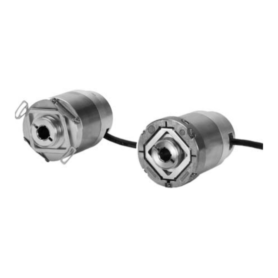
Rotary encoders for potentially explosive atmospheres (ATEX).
Encoder per ambienti potenzialmente esposivi (ATEX).
PTB 08 ATEX 1094 X
II 2 G Ex d IIC T 120 °C Gb
II 2 D Ex tb IIIC T 120 °C Db
Mounting Instructions
Istruzioni di montaggio
ECN 413
ECN 413
EQN 425
EQN 425
4/2016
Advertisement

Related Manuals for HEIDENHAIN ECN 413


Summary of Contents for HEIDENHAIN ECN 413
- Page 1 Mounting Instructions Istruzioni di montaggio ECN 413 Rotary encoders for potentially explosive atmospheres (ATEX). ECN 413 Encoder per ambienti potenzialmente esposivi (ATEX). EQN 425 EQN 425 PTB 08 ATEX 1094 X II 2 G Ex d IIC T 120 °C Gb II 2 D Ex tb IIIC T 120 °C Db...
- Page 2 Page Inhalt Seite 3 Warnings Contents 10 Items supplied Sommaire Indice 12 Mounting Dimensions/Assembly 20 Specifications Indice 22 Pin Layout Page Pagina 3 Avvertenze 10 Standard di fornitura 12 Dimensioni di montaggio/Montaggio 20 Dati tecnici 22 Piedinatura Página Maße in mm Dimensions in mm Cotes en mm Dimensioni in mm...
- Page 3 Fix the cable permanently for operation (strain relief). Posare il cavo in modo fisso (fermacavo). Do not repair the encoder. If service is needed, send the encoder to HEIDENHAIN Service, Traunreut. Non riparare il sistema di misura. Per interventi di manutenzione inviare il sistema di misura...
- Page 4 Warnhinweise Warnings Recommandations Avvertenze Advertencias Achtung: Note: Mounting and commissioning is to be conducted by a qualified specialist under compliance with local safety regulations. In addition to this, the machine manufacturer or designer himself must define the other data required for final assembly (e.g.
- Page 5 Attention: Attenzione: Il montaggio e la messa in funzione devono essere eseguite da personale qualifucato nel rispetto delle norme di sicurezza locali. Inoltre, il costruttore della macchina deve definire le ulteriori procedure necessarie per completare il montaggio (ad esempio: sicurezza allentamento viti sì/no) di ogni specifica applicazione. I cavi posso essere collegati o scollegati solo in assenza di tensione.
- Page 6 Warnhinweise Warnings Recommandations Avvertenze Advertencias = High: Fault detection signal Segnale di malfunzionamento = Low: * The fault-detection signal is not reset until after the rotary encoder has cooled. La cancellazione del segnale di allarme avviene dopo il raffreddamento dell'encoder.
- Page 7 Vorsicht: > 100° C 110° C Attention: If the temperature at the thermal switch (integrated in the encoder flange) exceeds 100 °C (± 5 K), the output signals remain available. A temperature at the thermo switch of 110° C (± 5 K) switches off the supply voltage. Operation with position feedback is then no longer possible.
- Page 8 Warnhinweise Warnings Recommandations Avvertenze Advertencias If the cable exit is subject to possible load, mount the protective cover s. (Directive 94/9/EG till 19.04.2016 / Directive 2014/34/EU from 20.04.2016). Qualora il passacavo sia esposto ad una possibile sollecitazione esterna, è necessario applicare il cappuccio di protezione s. (Direttiva 94/9/EG fino al 19.04.2016 / Direttiva 2014/34/EU dal 20.04.2016).
- Page 9 Protective cover included in delivery Cappuccio di protezione incluso nello standard di fornitura...
- Page 10 Lieferumfang Items supplied Objet de la fourniture Standard di fornitura Suministro Order separately: Accessori per il montaggio Ordinare separatamente: Clamping ring to be ordered separately if needed Commander séparément la bague de serrageÊsi nécessaire : In caso di necessità, ordinare l’anello di serraggio a parte:...
- Page 11 Lieferumfang Items supplied Objet de la fourniture Standard di fornitura Suministro Clamping ring to be ordered separately if needed Commander séparément la bague de serrageÊsi nécessaire : In caso di necessità, ordinare l’anello di serraggio a parte:...
- Page 12 Anbaumaße Mounting Dimensions Cote d'encombrement Dimensioni di montaggio Medidas para el montaje ¬ 6 À Connecting part for equipotential grounding and bonding according to DIN EN 60079-0 Collegamento per messa a terra e equipotenziale secondo DIN EN 60079-0...
- Page 13 Kundenseitige Anschlussmaße Required mating dimensions Conditions requises pour le montage Dimensioni di collegamento lato cliente Cotas de montaje requeridas Á Á Bearing Cuscinetto Á Opening for driving the clamping screw Foro di servizio per azionamento della vite di serraggio...
- Page 14 Montage Assembly Montage Montaggio Montaje Groove on clamping ring must remain visible. Le scanalature sull'anello di bloccaggio devono rimanere visibili.
- Page 16 Anbaumaße Mounting Dimensions Cote d'encombrement Dimensioni di montaggio Medidas para el montaje ¬ 6 À Connecting part for equipotential grounding and bonding according to DIN EN 60079-0 Collegamento per messa a terra e equipotenziale secondo DIN EN 60079-0...
- Page 17 Kundenseitige Anschlussmaße Required mating dimensions Conditions requises pour le montage Dimensioni di collegamento lato cliente Cotas de montaje requeridas Bearing Cuscinetto Á Á Protect against contact, (EN 60529). Prestare attenzione alla protezione, (EN 60529).
- Page 18 Montage Assembly Montage Montaggio Montaje Groove on clamping ring must remain visible. Le scanalature sull'anello di bloccaggio devono rimanere visibili. Achtung: Warning: Risk of injury from rotating parts. Protect against contact! Attention: Attenzione: pericolo di lesioni da pezzi rotanti. Mettere protezioni per impedire il contatto! Atención:...
- Page 20 Technische Kennwerte Specifications Caractéristiques techniques Dati tecnici Datos técnicos † † 25...
- Page 21 Bending radius Cables R Piegatura R Ø 6 mm R ‡ 20 mm > 100 mm > 100 mm > 200 mm Minimum distance from sources of interference Distanza minima dalla fonte di disturbo...
- Page 22 Anschlussbelegung Pin Layout Raccordements Piedinatura Distribución del conector Sensor Sensor CLOCK CLOCK A– B– DATA DATA Internal shield Connect with 0 V of the subsequent electronics Schermo interno Collegare 0V con l’elettronica successiva...
- Page 23 Vacant pins or wires must not be used! I pin o i fili inutilizzati non devono essere occupati! External shield connected to housing Schermo del cavo collegato alla carcassa The sensor line is connected inside the encoder to the supply line. La linea del sensore è...
- Page 24 DR. JOHANNES HEIDENHAIN GmbH 83301 Traunreut, Germany Technical support Measuring systems { TNC support NC programming PLC programming { Lathe controls www.heidenhain.de *I1041491-92*...
Need help?
Do you have a question about the ECN 413 and is the answer not in the manual?
Questions and answers