Table of Contents
Advertisement
Quick Links
Advertisement
Table of Contents
Troubleshooting

Related Manuals for Tuttnauer TIVA8-MD


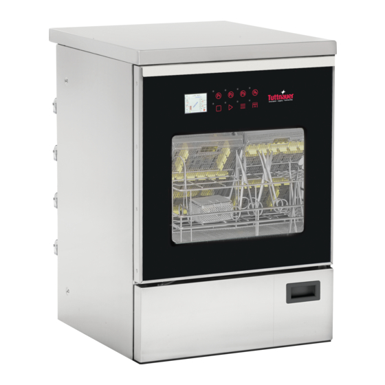
Summary of Contents for Tuttnauer TIVA8-MD
- Page 1 WASHER DISINFECTOR TIVA8 - MD INSTRUCTIONS FOR USE Original instructions Code Man205-0745009EN - Rev. 02 Before starting to operate with Edit. 06-2022 the washer disinfector, read Language: English these instructions for use Firmware version: 00B03...
- Page 2 This data must always be quoted when requesting assistance and/or spare parts to the Manufacturer. Manufacturer: Tuttnauer Ltd. Har-Tuv B Industrial Zone P.O Box 170 Beit Shemesh 9910101, Israel Tel. 972 2 9904611 - Fax 972 2 9904700 US Office: Tuttnauer USA Co.Ltd.
-
Page 3: Table Of Contents
Index 1 Symbols used in the manual ....4 6.4 Starting the machine..... . 24 2 Presentation . -
Page 4: Symbols Used In The Manual
Operative Instructions 1 Symbols used in the manual WARNING! The manufacturer also declines any and all liability for failure to comply Actions of particular importance or of potential risk and with the safety and prevention regulations danger are highlighted in the manual with a symbol provided by the legislation and the provisions whose meaning is set out below. -
Page 5: Field Of Application
Operative Instructions 2.1 Field of application Symbol Description This machine, intended for washing and disinfecting, Date of manufacture of the device. is considered a class IIb medical device (as defined by Directive 93/42/EEC class IIb). Device serial number from the Follow the instructions of the instrument manufacturers manufacturer. -
Page 6: Warranty Exclusions
Operative Instructions related repair request. - If chemicals not identified by the manufacturer as - Without prejudice to the Customer’s right of warranty compatible with the product are used. service in the above terms, it is expressly excluded Without limiting the generality of the provisions above, that the Customer may request termination of the Purchaser acknowledges that Seller does not install or contract, replacement of the product or reduction of... -
Page 7: Product Analysis
Operative Instructions a program (USER PIN MANAGEMENT option on • The validation of the product was made by the request). manufacturer in compliance with standard ISO 15883. • SUPER USER: Is the user that has special access to the • The machine does not cause harmful vibrations. device's menu for extra settings. -
Page 8: Technical Data
Operative Instructions • Steam condenser: 0.08 US gal (0.3 l). Colony-forming units (CFU) < 100 for 100 ml (*) • Machine without water softener: 0.11 US gal (0.4 l). • Machine with water softener (resins and salts): 0.4 US (*) for rinsing after disinfection phase, the maximum gal (1.6 l). -
Page 9: Accessories
Operative Instructions 2.7 Accessories The machine leaves the factory with the following accessories: Fig. 3e Fig. 3a Fig. 3b The user must request the most suitable accessory from the manufacturer: Fig. 3f Fig. 3c Fig. 3g - 3a: Washing rack positioned at the lower level, basic version. -
Page 10: Machine Stand
Operative Instructions 2.8 Machine stand 3.1 General warnings The washer disinfector can be customized with a 3.1.1 User obligations stand that provide an ergonomics height of 57.5" (146 • The user undertakes to entrust the machine only to cm). It can be used when the machine is not installed qualified and trained personnel. -
Page 11: Maintenance Service Personnel Obligations
Operative Instructions understood the information in this manual, as well as the instructions explicitly indicated in this manual. by unskilled personnel who are not in good mental • In case of long outage periods of the machine, please and physical health. cut the power supply off and close the water taps. - Page 12 Operative Instructions Each package, on the outside, shows the machine handling instructions in brief. During storage or handling the contents are not sterile. Upon delivery, check that the washer disinfector is intact and that the material indicated in the delivery document is actually present.
-
Page 13: Storage
Operative Instructions - Handle the machine with appropriate trolley. Lock the appropriate final destination, which may be recovery or machine on the trolley with a sturdy belt (Fig. 5.3) storage in landfills. Do not lift the machine by grasping it from the 4.1 Storage protruding points, such as the control panel. -
Page 14: Under The Counter Installation
Operative Instructions 5.2 Electrical connection supply taps, drain and anything else needed. - These components should have all the needed features and should be installed at the locations HAZARD! Only qualified and experienced shown in the installation scheme. personnel can connect the machine to the mains supply, in compliance with the current WARNING! The use of unsuitable parts, laws and regulations. -
Page 15: Electrical Connection
Operative Instructions - The machine is equipped with a terminal identified by the relative symbol for equipotential connections between appliances (see rules for electrical plants). - Connect the machine by using the power cable supplied with the machine. - In case of prolonged use of the machine it is recommended that you execute the disconnection procedure of the electrical connection by placing the dedicated safety device in “OFF”... - Page 16 Operative Instructions WHO. A high iron content can cause rust on the load supply is correct, otherwise proper washing of and in the special washing machine. If industrial water materials cannot be ensured. The connections for contains a higher amount of chlorides than 100 mg/l, cold and hot water must not feed any equipment the risk of corrosion significantly increases.
-
Page 17: Acquastop System
Operative Instructions WARNING! The flow pipes must not be WARNING! During this operation, check that shortened or damaged. the plastic cap is closed. 4) Insert the rack and start a normal washing cycle. The water supply taps must be capable of quickly The machine regenerates automatically. -
Page 18: Automatic Regeneration
Operative Instructions 6) Thoroughly clean the edge of the salt tank. 1) Hose connection waste water. 7) Tighten the cap again. 2) Hose connection capacitor discharge machine. 8) Run a «Prewash» program to clean the salt residues 3) Minimum connection point 3.9" (100 mm). inside the wash chamber. -
Page 19: Drain Connection
Operative Instructions 5.4.1 Drain connection 2) Mesh filter. 3) Chamber bottom filter. The waste connection must be properly installed 4) Salt tank cap. according to the applicable instructions. Insert the supplied filters in the specific positions. Constantly check the cleanliness of the filters, especially WARNING! If the waste connection is the chamber bottom filter (3 Fig. -
Page 20: Chemicals
Operative Instructions agents and caustic substances. - In case of contact with liquids, consult the instructions provided with the product. - Use only suitable liquids for cleaning equipment. Carefully follow the manufacturer’s information. - Keep chemicals out of the reach of children and outsiders. -
Page 21: Using The Machine
6) After running 3-4 washing tests, clean the water filters placed in the lower compartment of the Manufacturer: Tuttnauer machine (Fig. 11). Detergent T-Clean Tiva Detergent 7) Check that the drain trap does not show water leaks... -
Page 22: Before Use
Operative Instructions 4) Wait a few seconds to see in the lower right part, Release the door: the area where the chemical inlet holes are present, 1) Push the key supplied in the pack horizontally into a constant flow free from air bubbles. the gap between the door and the lid or worktop (1 5) Release the button and repeat the sequence from Fig. -
Page 23: Summary Of The Rack Loading Operations
Operative Instructions washing all residues well (e.g. disinfectant solutions) - Carefully place the load in the supports. in cold water. - Objects must not be put inside each other nor cover - Remove non-water soluble residues such as each other. Do not place objects so close to each composites, cement and amalgam in compliance with other that they cannot be washed properly. -
Page 24: Treatment Of Ophthalmic Instruments
Operative Instructions 6.3 Programs - The air and spray channels must be clean. - Finally, carry out a test. The machine leaves the factory with presetting washing Use the recommended liquids (see chapter "Using and programs already entered in the settings menu. Storing Chemicals"). -
Page 25: Starting The Program
Operative Instructions Wash - Close the door and push it until the lock is activated. The door can be unlocked and opened at any time It is the actual cleaning cycle. The cleaning chamber before the program starts, by pressing the Door key heats up until it reaches the specific temperature for (5 Fig. -
Page 26: Extracting The Load
Operative Instructions Ö IMPORTANT NOTE! Open door The control panel consists of 8 keys and a 3.5 inch LCD immediately after the end of the program to display. All keys, except key "3", are multi-function, avoid condensation forming. depending on the action being performed in a specified state of the device. -
Page 27: Colors Of The Keys
Operative Instructions 7) Start Description of the display (Fig. 16): STD: enter the selected menu item; 1) The number of the running program is displayed SPC: continue to the next parameter; (e.g. P02 = program 2); SPC: "B" character for the custom password. 2) It displays the phase the machine is running. -
Page 28: Display Screens
Operative Instructions Fig. 17.1 If bluetooth has been disabled the following icon will be displayed: Fig. 17.2 For more information on bluetooth, see chapter "Bluetooth". 7.2.3 Display screens Fig. 18.2 After starting the machine, following the instructions in chapter "Starting the Machine", the display will show the images indicating step-by-step the operations in progress. -
Page 29: Program 2 Regular
Operative Instructions 7) Prewash phase begins. Fig. 18.5 Fig. 18.8 7.2.4 Program 2 Regular Phase 3 Phase 1 8) At the end of the prewash phase, the water is 5) The machine starts the automatic work cycle automatically discharged. and discharges any residual water present in the chamber. - Page 30 Operative Instructions Phase 6 10) Wash phase begins: the machine will rise the water temperature to the presetted value and will keep it 13) Self-loading of hot water. During the self-loading for the presetted time. phase the chamber will be filled. Fig.
- Page 31 Operative Instructions Phase 7 16) At the end of the rinse phase, the water is automatically discharged. Fig. 18.19 19) Disinfection phase begins: the machine will rise the water temperature to 194°F (90°C) and will keep it Fig. 18.17 for 5 minutes. Phase 8 17) Self-loading of deionized water.
-
Page 32: Alarm Messages
Operative Instructions Phase 10 21) Dry phase begins: hot air is blown inside the chamber at a preset temperature and kept for the preset time. Fig. 19 If the program is interrupted because of an alarm, the display will show the message «No disinfection stop- alarm». -
Page 33: Settings
Operative Instructions The keys and their operation are shown below, contextualised according the menu in which you are located: - Use P1 and P2 to navigate up and down the menu. - Press START to access the entry of the menu selected. - Within the parameter, use the P1 and P2 keys to change the value of the highlighted parameter. -
Page 34: Procedure For Password Change
Operative Instructions 7.3 Alarms See Annex 12.6. 7.4 Warnings See Annex 12.7. 8 Software Desktop 8.1 General informations On request, the washer disinfector comes with a desktop software, called "WasherRePortal", that gives enhanced features to the User. With this software, in fact, it's possible to: - create and print digital versions of the reports;... -
Page 35: Plugs
Operative Instructions 9 Plugs at a time. • TPT3: The PT1000 3 probe is the probe for air heater. 9.1 USB plugs The value increases by 1°C at a time. • ERR - Alarms: 0000 means that the machine is not in an alarm state. -
Page 36: Loading The Printer Paper Roll
Operative Instructions 10 Loading the printer paper roll To change the paper roll, proceed as follows: 1) Open the printer cover leverin on the cover lateral projections. Fig. 25.4 11 Maintenance 11.1 General information Maintenance is a set of periodic and predefined Fig. -
Page 37: Personal Protective Equipment (Ppe)
Operative Instructions 11.2 Routine maintenance WARNING! Periodic maintenance is carried out by the technician under guarantee only if Routine maintenance operations are performed by the uilizer has correctly and regularly carried the user and includes all those jobs needed to keep out all ordinary maintenance operations and the machine clean and functioning. -
Page 38: Cleaning The Air Suction Filter
Operative Instructions 2) Loosen and remove both spray arms. in compliance with EN 1822. 3) Rinse the spray arms thoroughly. 4) Reassemble and tighten in position the spray arms. WARNING! It is mandatory to replace the prefilter and the HEPA H14 filter as WARNING! It is mandatory to record indicated in the Maintenance Logbook. -
Page 39: Equipment Disposal
Operative Instructions 11.5 Equipment disposal - Description of the part and required quantity. - Shipping method. If this item is not specified, the manufacturer, although dedicating particular care to this service, is not liable for any shipping delays due to force majeure. Shipping costs are always charged to the recipient. -
Page 40: Annexes
Operative Instructions 12 Annexes 12.1 Menu parameter table Factory Parameter Name Description Default GENERAL Turns the buzzer on or off at the end of End cycle buzzer 0=OFF 1=ON a cycle Warning alarm Turns the buzzer on or off when an 0=OFF 1=ON buzzer... - Page 41 Operative Instructions Factory Parameter Name Description Default Selects the program to be combined Program button 2 with button 2 Selects the program to be combined Program button 3 with button 3 Selects the desired language for the Printer language ENGLISH printer Enables or disables the drying stage Drying enable...
- Page 42 Operative Instructions Factory Parameter Name Description Default Hot water filling Sets the timer for the pump in the 1000 time absence of the flowmeter count seconds Deionized water Enables or disables the deionized water 0=OFF 1=ON flowmeter flowmeter Deionized water Sets the timer for the pump in the 1000 filling time...
- Page 43 Operative Instructions Factory Parameter Name Description Default Number of cycles performed with program... Number of cycles performed with Program cycles 40 program 40 USER PIN To set the user password, press the Pin User 1 RESET key and enter the 6 desired numbers Pin User 2 Pin User 20...
-
Page 44: Menu Structure
Operative Instructions 12.2 Menu structure S����-�� ���� (����� ��� �� �������) P���� P�� (5 �.) �� ����� �� ��� ���� ���� G������ End cycle buzzer Program bu�on 1 Warning alarm buzzer Program bu�on 2 Bu�ons noise Program bu�on 3 Device 1 Printer language Device 2 Drying enable... -
Page 45: Procedure For Password Change
Operative Instructions 12.3 Procedure for password change D��� O��� P���� S���� (3 �.) P���� D��� �� ���� Select User Y�� User Blocked? N� P���� D��� �� ���� Press Start to confirm P���� D��� �� ���� Enter old password P���� D��� ��... -
Page 46: Procedure For User Password Setup For The Super User
Operative Instructions 12.4 Procedure for user password setup for the super user S����-�� ���� (����� ��� �� �������) P���� P�� (5 �.) P���� D��� Insert Super User �� ���� password (max 3 a�empts) N� valid? Y�� See password change Y�� is expired or procedure first access? -
Page 47: Procedure For Super User Password Change
Operative Instructions 12.5 Procedure for super user password change S����-�� ���� D��� O��� (����� ��� �� �������) P���� P�� (5 �.) P���� D��� Insert Super User �� ���� password (max 3 a�empts) Y�� Password See password change expired? procedure N� P����... -
Page 48: Alarm Table
Operative Instructions 12.6 Alarm table ALARM DESCRIPTION ACTION 1- Press RESET EEPROM ALARM Firmware installed successfully. 2- Install new dataset A blackout occurred during cycle BLACKOUT execution and the program was Press RESET stopped. The door is open or unlocked. Press RESET DOOR OPEN Close the door. - Page 49 Operative Instructions ALARM DESCRIPTION ACTION The load might not be dried because Press RESET DRY TEMPERATURE the minimum set temperature has If it persists, call the service personnel. not been reached. A too high temperature was detected Press RESET PREWASH TEMPERAT during the prewash phase.
-
Page 50: Warnings Table
Operative Instructions ALARM DESCRIPTION ACTION Chemical liquid tank 4 is empty. Press RESET PRODUCT 4 EMPTY Add liquid. If it persists, call the service personnel. The spray arm marked in red on Press RESET SPRAY ARM LOCKED display is locked. Remove it and If it persists, call the service personnel. -
Page 51: Troubleshooting
Operative Instructions 12.8 Troubleshooting PROBLEM CAUSE SOLUTION The machine does not The fuse / circuit breaker of the Enable the fuse / switch of the electrical start electrical system has tripped. system. The program does not Door not closed correctly. Check door closure. -
Page 52: Rs232 Lan Connection
Operative Instructions 12.10 RS232 Lan Connection Example Managed by Byte Type Description Unit the machine Byte Value “@” = Start character Program selected Type phase in execution PT1000-1 temperature TPT1 76.6 °C (chamber work probe) PT1000-2 temperature TPT2 31.0 °C (chamber control probe) PT1000-3 temperature TPT3... - Page 53 Operative Instructions Example Managed by Byte Type Description Unit the machine Byte Value VDP4 Doser quantity 4 VDP5 Doser quantity 5 Cold water quantity liters Hot water quantity liters Deionized water quantity liters CONP Conductivity probe status Value 6180 Spray arm at the bottom of the SPRYR.B chamber rotation monitoring SPRYR.1...
- Page 54 Operative Instructions Example Managed by Byte Type Description Unit the machine Byte Value Spray arm at the top of the chamber SPRYR.A rotation monitoring CHPRS Chamber pressure 0.50 TRPRS Trolley pressure 1.00 Checksum "0x2A" = "*" = Stop character "0x0D" = "CR" = Carriage return PRG: PROGRAM SELECTED 0000 ………...
- Page 55 Operative Instructions REMT: PROGRAM REMAINING TIME 0000 ……… 0 minutes until program end …….. minutes until program end 0001 0120 1 minute until program end 120 minutes until program end 0002 2 minutes until program end PRP: WASHING PUMP PRESSURE 0000 0002 Pressure not measured...
- Page 56 Operative Instructions Notes...
- Page 57 Operative Instructions Notes...
- Page 58 Operative Instructions Notes...
- Page 59 Operative Instructions...
- Page 60 Tuttnauer USA Co.Ltd. 25 Power Drive Hauppauge, N.Y. 11788, USA Tel. +1 631 737 48 50 / +1 800 624 58 36 Fax +1 631 737 07 20 Web: www.tuttnauerusa.com...
Need help?
Do you have a question about the TIVA8-MD and is the answer not in the manual?
Questions and answers