Table of Contents
Advertisement
Quick Links
Advertisement
Table of Contents

Related Manuals for Ulma PLATFORM KSP


Summary of Contents for Ulma PLATFORM KSP
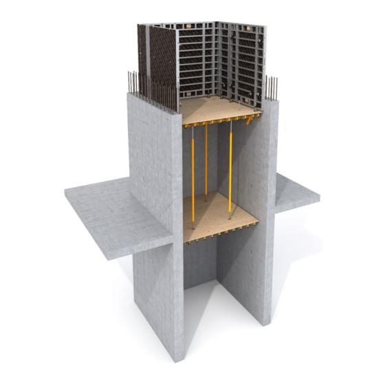
- Page 1 USER GUIDE PLATFORM KSP SHAFT INTERNAL FORMWORK...
- Page 2 Neither the whole nor any part of this document may be reproduced or transmitted in any form or by any means (electronic or mechanical), including photocopy, recording or any other form of information storage or retrieval system without the permission of ULMA Construction. © Copyright by ULMA C y E, S. Coop...
-
Page 3: Table Of Contents
TABLE OF CONTENTS 1. PRODUCT DESCRIPTION ..................4 2. COMPONENTS AND ACCESSORIES ................5 2.1. GRAPHIC DESCRIPTION ....................5 2.2. ELEMENTS DESCRIPTION ....................9 3. ASSEMBLY, USE AND DISASSEMBLY ..............11 3.1. MAIN PLATFORM ......................11 3.2. MAIN PLATFORM PERFORMANCE ................13 3.3. -
Page 4: Product Description
One of its special features is that by using the gravity pawl bracket and the different ULMA walers it is possible to cover a wide range of spans in this kind of internal hollows. -
Page 5: Components And Accessories
KSP SHAFT PLATFORM 2. Components and accessories 2.1. GRAPHIC DESCRIPTION Weight Weight Code Name Code Name (kg) (kg) WALL FIXING BRACKETS DU-100 WALERS 0306032 GRAVITY PAWL BRACKET 1960006 WALER DU-100/0.5 1960007 15.4 WALER DU-100/0.75 1960010 20.5 WALER DU-100/1 1960012 25.8 WALER DU-100/1.25 1960015 31.1... - Page 6 KSP SHAFT PLATFORM Weight Weight Code Name Code Name (kg) (kg) HM BEAMS 0190504 BEAM HM-050(4C) 0191004 BEAM HM-100(4C) 0191504 19.2 BEAM HM-150(4C) 0192004 24.5 BEAM HM-200(4C) 0192504 29.7 BEAM HM-250(4C) 0193004 34.9 BEAM HM-300(4C) 0193504 40.1 BEAM HM-350(4C) 0194004 45.3 BEAM HM-400(4C) Yellow painted...
- Page 7 KSP SHAFT PLATFORM Weight Weight Code Name Code Name (kg) (kg) 1960130 31.8 PUSH PULL PROP E 2.15-2.75 0333011 LADDER HANGER 1960125 36.4 PUSH PULL PROP E 2.7-3.3 1960410 42.9 PUSH PULL PROP E 3.25-4 Black painted and zinc coated 0260505 SIMPLE BRACING Black painted and zinc coated...
- Page 8 KSP SHAFT PLATFORM Weight Weight Code Name Code Name (kg) (kg) 7238001 0.22 EXAG NUT 15 0242483 0.38 BOLT M24X80 DIN-933-10.9 1901080 CONE DW 15/M24 Zinc coated Bichromate coated 0306022 11.4 SCREW JACK TR35X5/VM 0230104 0.16 TIE ROD 15/0.1 1901027 0.14 PIN Ø16X65 0230014...
-
Page 9: Elements Description
KSP SHAFT PLATFORM 2.2. ELEMENTS DESCRIPTION 2.2.4. Adjustable slab bracket (0306059) It is used in those cases where one side of the platform 2.2.1. Gravity Pawl Bracket (0306032) is supported on an existing slab. This is the basic element of this system. It is used to support the platform on the wall. - Page 10 KSP SHAFT PLATFORM 2.2.9. GP retrievable box out (0306002) 2.2.13. Plate 250x250x4 (0306005) It is installed from the internal formwork face keeping It is a distribution plate on which the different screw jacks rest. It allows better sliding and moving of these in mind that a hole of 155x205 is needed on the panel plywood.
-
Page 11: Assembly, Use And Disassembly
KSP SHAFT PLATFORM 3. Assembly, Use and Disassembly 3.1. MAIN PLATFORM 3.1.1. Gravity pawl bracket and Adjustable bracket The first step in the KSP platform assembly is to fix the Gravity Pawl Brackets, the Adjustable Brackets or the Short Gravity Pawls on the waler. 0250000 0252070 The connection is done by two E20x70 pins with their... - Page 12 KSP SHAFT PLATFORM 3.1.2. Walers positioning Once the brackets are assembled on the walers, the next operation consists of positioning the walers. In order to do it properly, some timber planks should be used to support the set, preventing the Gravity pawl from touching the floor.
-
Page 13: Main Platform Performance
KSP SHAFT PLATFORM It is recommended to adjust the board taking into account that the distance from its edge to the wall will be approximately 50mm. These chains are directly fixed on the waler by a E20x70 pin (this pin will be an extra pin different to the ones used to fix the Gravity pawl bracket). - Page 14 KSP SHAFT PLATFORM 3.2.1. GP Box Out: To be able to insert the main platform into the shaft, pawl brackets have to be previously folded. The best way is to tie the mobile part of the pawl to the waler using cords.
-
Page 15: Cone Recovery Platform
KSP SHAFT PLATFORM 3.2.2. Folding bracket After the first pouring formwork panels are stripped off; the Folding Bracket can be fixed to these cones embedded in the concrete wall with an M24x80 bolt. Once the Folding brackets are fixed to the cones in the wall and as they stand out of the wall, the main platform can be inserted in the shaft and left resting through the Adjustable brackets of the platform on... - Page 16 KSP SHAFT PLATFORM There are three different connection types between main platform and cone recovery platform: • Connection by BRIO standards • Connection by push-pull props E • Connection by DW15 tie rods • Connection by BRIO standards: BRIO HEAD/DU and BRIO scaffolding standards are In these cases the best option is to preassemble BRIO used for this solution: HEAD/DU on the main and cone recovery platforms.
- Page 17 KSP SHAFT PLATFORM • 1960130 push-pull prop 2.15-2.75 • 1960125 push-pull prop 2.7-3.3 • 1960410 push pull prop 3.2-5.4 The push-pull props E are fixed to the waler by means of E20x70 pins The platforms may be covered with boards such as three-layer timber boards or wood planks.
-
Page 18: Formwork Panels Positioning
KSP SHAFT PLATFORM 3.4. FORMWORK PANELS POSITIONING The formwork panels’ vertical adjustment is done by fixing two levelling jacks at the bottom of each gang. There are 4 different types of jacks depending on formwork type, all of them are driven by a 24 wrench •... -
Page 19: Formwork Panel Plumbing
KSP SHAFT PLATFORM 3.4.3. Levelling jack TR35x5/ORMA The usual bracing way is with two of these push-pull prop sets per gang. It is recommended to place all It is used for levelling ORMA formwork panels. It is inclined push-pull props in one set parallel to each fixed to the panel rib with a 20x85 pin and an R/4 other in order to facilitate the set’s plumbing. - Page 20 KSP SHAFT PLATFORM 3.6.2. Separately Each formwork system must be used with its corresponding approved lifting The formwork and the platform are not connected, hook so finally they move independently. 3.6.1. Complete set Formwork is connected to the main platform by chains.
-
Page 21: Solutions
KSP SHAFT PLATFORM 4. Solutions 4.1. MAIN PLATFORM SUPPORTS When climbing with KSP platforms, it is necessary to provide supports for the platforms on the wall. This support can be created by leaving a cavity in the wall It is very important to guarantee a where brackets can rest (BOX-OUT solution) or fixing minimum support of 50mm an articulated bracket on the wall with embedded... - Page 22 KSP SHAFT PLATFORM The Folding Bracket must be correctly fixed to the wall and the minimum support of the Adjustable Bracket must be 50mm The stability of the platform should always be When using this box-out, it is necessary to drill a verified in the worst case (platform moved to the top 205x155 hole in the formwork panel.
- Page 23 KSP SHAFT PLATFORM 4.1.2. GP box out The box is placed from the concrete face of the formwork and fastened with a short pin 0.35m and hexagonal nut 15. To do so, a 18mm hole has to be drilled through the plywood. This part remains in the concrete and only removing the short pin 0,35m and stripping the formwork a few millimetres from the wall, the formwork set can be...
-
Page 24: Cone Recovery Platform
KSP SHAFT PLATFORM Exag. Nut DW15 Plate Washer Nut 15 For this solution, it should be kept in mind that the Folding bracket stands out of the wall approximately Push-Pull Prop E 100 mm. This is the reason why for lifting the set, the formwork has to be rolled-back at least 100-150 mm. -
Page 25: Adjustable Slab Support
KSP SHAFT PLATFORM 4.3. ADJUSTABLE SLAB SUPPORT This solution can be applied in those cases where there is an already poured slab. One side of the platform is supported on the slab. For these cases MK-120, MK-180, DU-100 or DU-120 walers can be used. -
Page 26: Features
KSP SHAFT PLATFORM 5. Features 5.1. MAIN PLATFORM – GEOMETRY For main platform lay-out, a minimum 50 mm gap between the edge of the plywood and the wall has to be considered due to possible concrete imperfections. 5.2. HOLLOW LENGTHS 5.2.1. - Page 27 KSP SHAFT PLATFORM Depending on the loads (see point 5.3) and hollow lengths, DU-100, MK-120, DU-120 or MK-180 walers should be chosen. Hollow lengths covered by the different walers with Gravity Pawl Brackets are: DU-100 DU-120 MK-120 MK-180 HOLLOW HOLLOW HOLLOW HOLLOW WALER...
- Page 28 KSP SHAFT PLATFORM For smaller hollows, where it is impossible to use the GRAVITY PAWL, SHORT GRAVITY PAWL should be used taking into account the following dimensions: M20 bolts have to be used instead of E20x70 pins when MK-0.5, MK-0.625, MK-0.75, MK- 0.875 profiles or waler DU-120/0.7 are used.
- Page 29 KSP SHAFT PLATFORM 5.2.2. Adjustable Bracket & Folding Bracket The smallest hollows where a platform using the Folding Bracket can be installed are: DU-100 DU-120 MK-120 MK-180 Minimum 1. m 1. m 1.15 m 2.125m lengths 1.35 m 1.45 m 1.35 m 2.55 m Depending on the loads (see point 5.3) and hollow lengths, DU-100, MK-120, DU-120 or MK-180 walers should be...
- Page 30 KSP SHAFT PLATFORM Smaller hollow lengths can be solved as follows: 5.2.3. Examples 2m hollow solved with DU-100 WALER...
- Page 31 KSP SHAFT PLATFORM 3m hollow solved with DU-120 WALER 3m hollow solved with MK-120 WALER...
- Page 32 KSP SHAFT PLATFORM 5.4m hollow solved with MK-180 WALER 2.3 x 5.6 m hollow top view...
-
Page 33: Maximum Loads
KSP SHAFT PLATFORM 5.3. MAXIMUM LOADS In this section a simplified way to calculate and verify KSP Platforms is shown. Is responsibility of each engineer to check that all the simplification hypotheses made in this example (see 5.3.2 “Clarifications…”), are applicable to its particular case. 5.3.1. - Page 34 KSP SHAFT PLATFORM 5.3.2. Working loads Gravity Pawl Bracket (pin separation ≥ 250mm): • KSP Shaft Platform Distributed load (SLS) on the waler DU 100 MK 120 DU 120 MK 180 Hollow length (m) Notes about the diagram: 1. This graphic is valid for shaft platforms formed by Gravity Pawl Bracket (0306032), being connected to the waler with pins separated ≥...
- Page 35 KSP SHAFT PLATFORM 3. Cone recovery platform. This diagram is valid for : *Without cone recovery platform: for any hollow length * With cone recovery platform: for hollow lengths >2.1 m (the distance of the connection pin must be ≤ 525 mm from the wall). •...
- Page 36 KSP SHAFT PLATFORM GRAVITY PAWL BRACKET (pin sep. =200mm) ADJUSTABLE BRACKET + FOLDING BRACKET SHORT GRAVITY PAWL BRACKET 2- The values in this table are calculated assuming that for all configurations, the Gravity Pawl Bracket, the Adjustable Bracket and Short Gravity Pawl are in the position shown in the picture below (the most unfavourable position).
- Page 37 KSP SHAFT PLATFORM 5- Cone recovery platform. This diagram is valid for : *Without cone recovery platform: for any hollow length * With cone recovery platform: for hollow lengths >2.1 m (the distance of the connection pin must be <525 mm from the wall). 5.3.3.
- Page 38 KSP SHAFT PLATFORM Once it has been verified that the reaction in the bracket is smaller than 25 kN, the cone DW15/ M24 strength should also be verified. NOTE: Respecting the minimum shear distances (c ), with h =185mm and 1,min.v 2,min.v 3,min.v...
- Page 39 KSP SHAFT PLATFORM The next step of the calculation is the reaction verification: A 10 Mpa concrete would be valid. This document only refers to the main beams and their supporting. Board and secondary beams have to be calculated by the user. This calculation is not included here.
-
Page 40: Conditions Of Use
• The formwork panels must be drawn in close to the • Guarantee appropriate order and cleanliness in the wall and fixed. formwork and shaft platform KSP to assure they are properly operated. Keep platforms clean and free of tools, bolts and other parts that could fall from... - Page 41 Additionally, they must have access to the user's technical drawings provided by ULMA. All bolts, guide at all times. connections, tie rods, pins, etc.. must be properly •...
- Page 42 All welding operations, which could have components to support or anchor the KSP shaft consequences on the functionality of the climbing platform. ULMA will not be held responsible for the system, must be performed with the supervision use of materials provided by third parties.
-
Page 43: Legal References
7. Legal references 7.1. LEGAL REFERENCES • Council Directive 89/391/EEC on the introduction of measures to encourage improvements in the safety and health of workers at work • Council Directive 89/654/EEC concerning the minimum safety and health requirements for the workplace. •... - Page 44 ULMA C y E, S. Coop. Ps. Otadui, 3 -Apdo. 13 05D120ENM 20560 Oñati, España T. +34 943 034 900 F. +34 943 034 920 www.ulmaconstruction.com...
Need help?
Do you have a question about the PLATFORM KSP and is the answer not in the manual?
Questions and answers