
Subscribe to Our Youtube Channel
Summary of Contents for Xylem CentriPro AQUAVAR CPC4 FD Series
- Page 1 SUPPLEMENT MANUAL IM250R02 AQUAVAR CPC - FD ® Variable Speed Drive with Fused Disconnect SUPPLEMENT TO THE INSTALLATION AND OPERATION MANUAL (IM167)
-
Page 2: Table Of Contents
TABLE OF CONTENTS SAFETY Use of Warnings and Notes ..............................3 INSTALLATION Application ....................................4 Input Disconnect Features and Functions ...........................4 Installation Flow Chart ................................6 Preparing for Installation (Supplement to Aquavar CPC-01/U1 User’s Manual) .............7 Installing the Drive (Supplement to Aquavar CPC-01/U1 User’s Manual) ...............9 Installing the Wiring (Supplement to Aquavar CPC-01/U1 User’s Manual) .............. -
Page 3: Use Of Warnings And Notes
SAFETY WARNING! The AQUAVAR CPC adjustable speed AC drive with Input Disconnect should ONLY be installed by a qualified electrician. WARNING! Even when the motor is stopped, dangerous voltage is present at the Power Circuit terminals U1, V1, W1 and U2, V2, W2 and, depending on the frame size, UDC+ and UDC-, or BRK+ and BRK-. WARNING! Dangerous voltage is present when input power is connected. -
Page 4: Installation
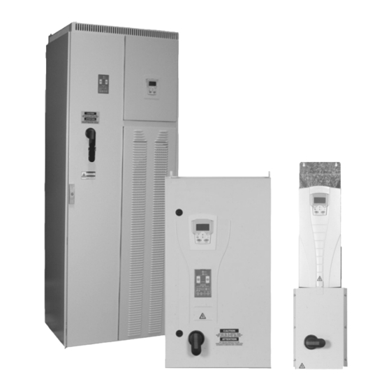
INSTALLATION Study these installation instructions carefully before proceeding. Failure to observe the warn- ings and instructions may cause a malfunction or personal hazard. WARNING! Before you begin read “Safety” on page 3. WARNING! When the Aquavar CPC with Input Disconnect is connected to the line power, the Motor Terminals T1, T2, and T3 are live even if the motor is not running. - Page 5 INSTALLATION The following figures show the front view of the Aquavar CPC Input Disconnect standard configurations and identify the major components. R1 … R4 R5, R6 R7, R8 NEMA 1 & 12 NEMA 1 & 12 NEMA 1 & 12 Enclosures Enclosures Enclosures...
-
Page 6: Installation Flow Chart
INSTALLATION Installation Flow Chart The installation of Input Disconnect configurations for Aquavar CPC drives follows the outline below. The steps must be carried out in the order shown. At the right of each step are refer- ences to the detailed information needed for the correct installation of the unit. NOTE! References in the middle column below are to the Aquavar CPC User’s Manual (IM167). -
Page 7: Preparing For Installation (Supplement To Aquavar Cpc-01/U1 User's Manual)
INSTALLATION Preparing for Installation (Supplement to Aquavar CPC User’s Manual) Lifting the Drive R7…R8 Frames WARNING! Handle and ship floor mounted enclosures only in the upright position. These units are not designed to be laid on their backs. 1. Use a pallet truck to move the package/enclosure to the installation site. 2. - Page 8 INSTALLATION Preparing for Installation (Supplement to Aquavar CPC User’s Manual) Drive Identification To identify the type of device you are installing, refer to the type code number on the device identification label. • Wall mounting base drives – label attached on the side surface of the heat sink. •...
-
Page 9: Installing The Drive (Supplement To Aquavar Cpc-01/U1 User's Manual)
INSTALLATION Suitable Mounting Location For selecting a suitable mounting location for FD configurations, refer to: • Preparing for installation in the Aquavar CPC User’s Manual, and • The Technical Data section of this manual for information on dimensions and weights. Installing the Drive (Supplement to Aquavar CPC User’s Manual - IM167) WARNING! Metal shavings or debris in the enclosure can damage electrical equipment and create a hazardous condition. -
Page 10: Installing The Wiring (Supplement To Aquavar Cpc-01/U1 User's Manual)
INSTALLATION Mount the Drive R7…R8 30º 1. Use a hoist to move the cabinet into position. NOTE! If the cabinet location does not provide access to the cabinet sides, be sure to re-mount side panels before positioning cabinet. 2. Install and tighten mounting bolts. PC00003 Installing the Wiring (Supplement to Aquavar CPC User’s Manual) WARNING! - Page 11 INSTALLATION Wiring Overview Power Connection – Standard Input Disconnect (R1…R6, Wall Mounted) The following figures show the Standard Input Disconnect (wall mounted) wiring connection points. Refer to the Aquavar CPC User’s Manual for control connections to the drive. R5, R6 R1…R4 Aquavar NEMA 1 &...
- Page 12 INSTALLATION Power Connection – Standard Input Disconnect (R7…R8, Floor Mounted) The R7 and R8 Aquavar CPC Standard Input Disconnect units are configured for wiring access from the top and include a removable conduit mounting plate. The following figure shows the Standard Input Disconnect (floor mounted) wiring connection points.
- Page 13 INSTALLATION Install the Line Input Wiring Line Input Connections – Standard Input Disconnect Configurations Connect input power to the terminals of the disconnect switch or circuit breaker. Connect the equipment grounding conductor to the ground lug. The figure below shows the connection points for Standard Input Disconnect configurations.
-
Page 14: Maintenance Maintenance Intervals
MAINTENANCE Maintenance Intervals If installed in an appropriate environment, the drive requires very little maintenance. This table lists the routine maintenance intervals recommended by CentriPro. Maintenance Configuration Interval Instruction Check/replace R5/R6 R5/R6 NEMA 12 Check every 3 “Frame Sizes R5/R6 – Enclosure enclosure inlet air filter enclosures months. -
Page 15: Enclosure Fan Replacement - Nema 12 Enclosures
MAINTENANCE Enclosure Fan Replacement – NEMA 12 Enclosures NEMA 12 enclosures include an additional fan (or fans) to move air through the enclosure. Frame Sizes R7/R8 – NEMA 12 Enclosures The enclosure fan is located in the exhaust box on top of the NEMA 12 enclosure. -
Page 16: Enclosure Air Filter Replacement - Nema 12 Enclosures
MAINTENANCE Enclosure Air Filter Replacement – NEMA 12 Enclosures Frame Sizes R5/R6 – Enclosure Inlet Air Filter This procedure applies to disconnect configurations in R5 and R6 frame sizes with NEMA 12 enclosures. This filter is located at the bottom of the enclosure. Use the following procedure to check and replace filters. - Page 17 MAINTENANCE 2. Lay the filter frame on a flat work surface. Remove the 3 retaining brackets by squeezing the tabbed corners in towards the middle of each bracket until the bracket clears the filter frame. Save these brackets for replacement. Remove and inspect the filter.
- Page 18 MAINTENANCE Frame Sizes R7/R8 – NEMA 12 Enclosure Exhaust Filters The exhaust filters in the R7/R8 NEMA 12 enclosure are located in the exhaust box at the top of the enclosure. There are 2 filter frames attached to the exhaust box. 1.
-
Page 19: Technical Data
TECHNICAL DATA Ratings (Supplement to Aquavar CPC User’s Manual - IM167) NOTE! The ratings listed below are exceptions to the ratings listed in the Aquavar CPC User’s Manual. Ratings, 380…480 Volt Drives Valid up to 40°C (104 °F) Type Code Normal Use Heavy-Duty Use Frame Size... -
Page 20: Input Power Connections (Supplement To Aquavar Cpc-01/U1 User's Manual)
TECHNICAL DATA Input Power Connections (Supplement to Aquavar CPC User’s Manual) Fuses NOTE! Although fuses listed are similar in functional characteristics to fuses listed in the Aquavar CPC User’s Manual, physical characteristics may differ. Fuses from other manufacturers can be used if they meet the functional characteristics of those in these tables. - Page 21 TECHNICAL DATA 380…480 Volt Fuses Base 380 … 480 Volt Drive Input Fuse Ratings Drive Amps Bussmann Frame Identification (600V) Type Size 1/1.5 CPC4???xFD KTK-R-15 CPC4???xFD KTK-R-15 CPC4006xFD KTK-R-15 CPC4008xFD KTK-R-15 CPC4012xFD KTK-R-15 CPC4015xFD KTK-R-30 CPC4023xFD KTK-R-30 CPC4031xFD JJS-50 CPC4038xFD JJS-50 CPC4044xFD JJS-100...
- Page 22 TECHNICAL DATA 500…600 Volt Fuses Base 500 … 600 Volt Drive Input Fuse Ratings Drive Amps Bussmann Frame Identification (600V) Type Size CPC5002xFD KTK-R-15 CPC5004xFD KTK-R-15 CPC5006xFD KTK-R-15 CPC5009xFD KTK-R-15 CPC5011xFD KTK-R-30 CPC5017xFD KTK-R-30 CPC5022xFD JJS-50 CPC5027xFD JJS-50 CPC5032xFD JJS-100 CPC5041xFD JJS-100 CPC5052xFD...
- Page 23 TECHNICAL DATA Drive’s Power Connection Terminals (Supplement to Aquavar CPC User’s Manual) The following tables show maximum wire size and required tightening torque for incomming power and motor terminals, and grounding terminal lug information. 208…240 Volt, Terminals 208 … 240 Volt Power Wiring Data Ground Dis-...
- Page 24 TECHNICAL DATA 380…480 Volt, Terminals 380 … 480 Volt Power Wiring Data Ground Dis- Frame Circuit Motor Lugs Type Code connect Size Breaker Terminals NEMA Switch 1 & 12 CPC4006xFD 62 in-lbs 7 in-lbs 12 in-lbs CPC4008xFD 35 in-lbs CPC4012xFD CPC4015xFD CPC4023xFD 62 in-lbs...
- Page 25 TECHNICAL DATA 500…600 Volt, Terminals 500 … 600 Volt Power Wiring Data Ground Frame Dis- Circuit Motor Lugs Type Code connect Size Breaker Terminals NEMA Switch 1 & 12 CPC5002xFD CPC5004xFD CPC5006xFD CPC5009xFD 62 in-lbs 7 in-lbs 12 in-lbs 35 in-lbs CPC5011xFD CPC5017xFD CPC5022xFD...
-
Page 26: Motor Connections
TECHNICAL DATA Motor Connections Motor Connection Specifications – R7/R8 Motor Connection Specifications Maximum Motor Cable Length* Frame Maximum Motor Size = 1 or 4 kHz = 8 kHz or 12 kHz Cable Length R7…R8 300 m 980 ft Does not apply WARNING! Using a motor cable longer than specified in the chart above may cause permanent damage to the drive. -
Page 27: Dimensions And Weights (Supplement To Aquavar Cpc-01/U1 User's Manual)
TECHNICAL DATA Dimensions and Weights (Supplement to Aquavar CPC User’s Manual) Mounting Dimensions NEMA 1 & 12, R1…R6 Mounting Dimensions R1…R4 R5/R6 See Detail A See Detail B DS0301 BP0057 Detail A Detail B NEMA 1 and NEMA 12 – Mounting Dimensions for each Frame Size Ref. - Page 28 TECHNICAL DATA NEMA 1 & 12, R7…R8 Mounting Dimensions NEMA 1 and NEMA 12 – Dimensions for each Frame Size R7 & R8 Ref. Top View 31.7 25.9 26.6 474.5 18.7 65.5 Mounting Hardware 11 mm 13/32 * Measurements are center to center. Weights The following table lists typical maximum weights for each frame size.
- Page 29 TECHNICAL DATA Outside Dimensions Outside Dimensions NEMA 1, R1…R4 Outside Dimensions DS0301 DS0302 Input Disconnect, NEMA 1, R1…R4 Dimensions Ref. 10.2 10.2 28.7 32.6 1013 39.9 1147 45.2 11.2 11.6 11.9 13.1 NOTE: -088A-2, -114A-2 and -097A-4 NEMA 1 & 12 units are R4 frame base drives in R5 enclosures. R5 enclosure information applies.
- Page 30 TECHNICAL DATA NEMA 12, R1…R4 Outside Dimensions DS0303 DS0304 Input Disconnect, NEMA 12, R1…R4 Dimensions Ref. 10.5 10.5 29.3 33.2 1030 40.6 1163 45.8 11.2 11.6 11.9 13.1 NOTE: -088A-2, -114A-2 and -097A-4 NEMA 1 & 12 units are R4 frame base drives in R5 enclosures. R5 enclosure information applies.
- Page 31 TECHNICAL DATA NEMA 1, R5/R6 Outside Dimensions BP0063 Input Disconnect, NEMA 1, R5/R6 Dimensions Ref. 28.1 28.1 47.7 1212 47.7 19.1 19.1 NOTE: -088A-2, -114A-2 and -097A-4 NEMA 1 & 12 units are R4 frame base drives in R5 enclosures. R5 enclosure information applies.
- Page 32 TECHNICAL DATA NEMA 12, R5/R6 Outside Dimensions BP0062 Input Disconnect, NEMA 12, R5/R6 Dimensions Ref. 28.9 28.9 1371 54.0 1371 54.0 19.1 19.1 NOTE: -088A-2, -114A-2 and -097A-4 NEMA 1 & 12 units are R4 frame base drives in R5 enclosures. R5 enclosure information applies.
- Page 33 TECHNICAL DATA NEMA 1 & 12, R7…R8 Outside Dimensions BP0017 Outside Dimensions by Frame Size Enclosure Ref. 31.7 31.7 NEMA 1 2125 83.7 2125 83.7 25.9 25.9 31.7 31.7 NEMA 12 2377 93.6 2377 93.6 25.9 25.9 Additional Free Space Recommendations In addition to the free space requirements for cooling (“Cooling - R7/R8”), allow: •...
-
Page 34: Applicable Standards
TECHNICAL DATA Applicable Standards Drive compliance with the following standards is identified by the standards “marks” on the type code label. Mark Applicable Standards UL 508C and UL Standard for Safety, Power Conversion Equipment, second C22.2 No. 14 edition and CSA Standard for Industrial Control Equipment ®... - Page 35 INDEX maintenance enclosure protection class code....8 drive module fan replacement ....14 enclosure, NEMA 12 enclosure fan replacement .
- Page 36 2881 East Bayard Street Ext., Suite A Seneca Falls, NY 13148 Phone: (800) 453-6777 Fax: (888) 322-5877 www.centripro.com CentriPro and Aquavar are trademarks of Xylem Inc. or one of its subsidiaries. DUSTLOK is a registered trademark of Fiberbond Corp. ® © 2012 Xylem Inc.
Need help?
Do you have a question about the CentriPro AQUAVAR CPC4 FD Series and is the answer not in the manual?
Questions and answers