
Related Manuals for Faber TIVANO TVNO30SS395


Summary of Contents for Faber TIVANO TVNO30SS395
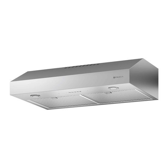
- Page 1 TIVANO Installation Instructions Use and Care Information Instructions d'installation Utilisez et d'entretien Instrucciones de instalación Información de uso y cuidado TVNO30SS395 TVNO36SS395...
-
Page 2: Table Of Contents
CONTENTS Section Page Important safety instructions Range Hood dimensions Installation height requirements Parts Tools needed Before Installation Remove Shipping Materials Only for canadian market Choose Vertical or Horizontal Electrical Connection Knockout's Choose Vertical or Horizontal Electrical Connection Knockout's Ducted venting method options Ducted - 7"... -
Page 3: Important Safety Instructions
IMPORTANT SAFETY INSTRUCTIONS READ AND SAVE THESE INSTRUCTIONS BEFORE YOU START INSTALLING THIS RANGE HOOD WARNING: - TO REDUCE THE RISK OF A RANGE TOP GREASE FIRE: a) Never leave surface units unattended at high settings. Boilovers cause smoking and greasy spillovers that may ignite. - Page 4 3. When cutting or drilling into wall or ceiling, do not damage electrical wiring and other hidden utilities. 4. Ducted fans must always be vented to the outdoors. ALL WALL AND FLOOR OPENINGS WHERE THE RANGE HOOD IS INSTALLED MUST BE SEALED. This Range Hood requires at least 24"...
- Page 5 ELECTRICAL REQUIREMENTS A 120 volt, 60 Hz AC-only electrical supply is required on a separate 15 amp fused circuit. A time-delay fuse or circuit breaker is recommended. The fuse must be sized per local ELECTRICAL INSTALLATION WITH WIRING BOX THIS UNIT MUST BE CONNECTED WITH COPPER WIRE ONLY. Wire sizes must conform local codes and ordinances.
-
Page 6: Range Hood Dimensions
RANGE HOOD DIMENSIONS RECTANGULAR OUTLET AIR... -
Page 7: Installation Height Requirements
CIRCULAR OUTLET AIR INSTALLATION HEIGHT REQUIREMENTS MIN. 24" OVER ELECTRIC / MIN. 30" OVER GAS Min.24” Min.30”... -
Page 8: Parts
PARTS PARTS INCLUDED REF. PART Hood body – Includes Controls, Light, Filters, Blower Damper ( 7" Round Flange Grid (Only for Canadian Market) REF PART... -
Page 9: Tools Needed
PARTS NEEDED PART 7" Round Metal Ductwork 7" Damper Wire connectors. Power Supply Cable. Drywall plugs or other suitable wall fasteners based on your installation. TOOLS NEEDED TOOL Tape Measure Pencil Phillips Screwdriver Torx Screwdriver Pozi Screwdriver... -
Page 10: Only For Canadian Market
ONLY FOR CANADIAN MARKET For ducted installations only: pulling down at the same time. Remove the screws as pictured. Remove two of the screws from the motor assembly housing as pictured. Install the screws as pictured. Install Grid with the two screws removed from step 2. Screw the protection grid into the location shown in the picture below. -
Page 11: Choose Vertical Or Horizontal Electrical Connection Knockout's
CHOOSE VERTICAL OR HORIZONTAL ELECTRICAL CONNECTION KNOCKOUT'S Preparing the hood for electrical knockouts a time by pushing them towards the back of the hood and pulling down at the same time. Remove the wiring box cover by unscrewing the 2 screws. Phillips Screwdriver... - Page 12 Choose the rear hole for the electric connection and break with a screwdriver or other tool. During the installation thread Power Supply Cable through this hole. Choose the top hole for the electric connection and break with a screwdriver or other tool.
-
Page 13: Ducted Venting Method Options
DUCTED VENTING METHOD OPTIONS DUCTED WITH 7" ROUND OUTLET: – Vertical – Horizontal 7" Rear Go to page 14 DUCTED WITH 3 1/4" X 10" RECTANGULAR OUTLET – Vertical – Horizontal Rear 10" 10" Go to page 16 NON DUCTED - RECIRCULATION OPTION Requires purchase of Activated Charcoal Accessory... -
Page 14: Ducted - 7" Round Outlet
DUCTED - 7" ROUND OUTLET 7" Rear Caution: If an elbow is required, do it as far away from the hood's exhaust opening as possible. Required; 7" Round Damper purchase separately. Cut where indicated. Remove both the rectangular and semicircle areas with metal shears. - Page 15 Install the Flange with Flange transition screws NOTE: The Flange must be mounted with the lip facing upward. Torx Screwdriver Install 7" Round Damper purchased separately. Secure damper with foil duct tape. Connect the 7" Round Metal Ductwork to the Roof or Wall Cap purchased separately and then attach ductwork.
-
Page 16: Ducted - 3 1/4" X 10" Rectangular Outlet On Top
DUCTED - 3 1/4" X 10" RECTANGULAR OUTLET ON TOP " x 10" Rear Caution: If an elbow is required, do it as far away from the hood's exhaust opening as possible. Choose the rectangular upper air outlet or rectangular rear air outlet and cut where indicated.(See page 18 for Rear Outlet) Install the included rectangular air outlet with two screws Connect the metal ductwork to the Roof or Wall Cap purchased separately and... -
Page 17: Ducted - 3 1/4" X 10" Rectangular Outlet Rear
DUCTED - 3 1/4" X 10" RECTANGULAR OUTLET REAR " x 10" Rear Caution: If an elbow is required, do it as far away from the hood's exhaust opening as possible. Use the rear air outlet and cut where indicated. Rear Install the included rectangular air outlet with two screws Connect the metal ductwork to the Roof or Wall Cap purchased separately and... - Page 18 NON DUCTED RECIRCULATION OPTION Remove the indicated blower cover (do not discard the screw). Cut the cover where indicated in picture b1. Discard / Recycle upper pieces of blower cover. Reinstall the modified blower cover with the same screw. Install the Activated Charcoal Filter purchased separately.where indicated in the picture "C". Required Activated Charcoal Filter Accessory - (FILTER5) purchased separately.
-
Page 19: Choosing The Mounting Method
CHOOSING THE MOUNTING METHOD Installation for Mounting on the Wall Page Installation for Mounting to the cabinet Page... -
Page 20: Mounting Range Hood On Wall
MOUNTING RANGE HOOD ON WALL DRAW POSITIONING LINES Draw a vertical line from the supporting back wall to the ceiling or upper limit, at the center of the area in which the hood will be installed. Draw a horizontal line from where the bottom edge of hood will be located, to a minimum of 24"... - Page 21 MOUNTING RANGE HOOD ON WALL Mark the wall for the upper anchors. line at distance on the left and right of the vertical line 30" = 27 30" = 27 " 36" = 33 36" = 33 " Mark the wall for lower anchors. Mark 1”...
- Page 22 MOUNTING RANGE HOOD ON WALL If fastener locations do not align with the studs, insert the purchased wall plugs in the holes. In upper holes use two of the supplied screws to secure the hood body to the wall. Pozi Screwdriver...
- Page 23 MOUNTING RANGE HOOD ON WALL Using two remaining screws anchor the hood in lower holes as indicated. Pozi Screwdriver...
-
Page 24: Mounting Range Hood Under The Cabinet
MOUNTING RANGE HOOD UNDER THE CABINET Locate the hole on the Range Hood for the power cord (See Section " CHOOSE VERTICAL OR HORIZONTAL ELECTRICAL CONNECTION KNOCKOUT'S ") and pass the cord through the appropriate hole. Top View 1" 5/16 1"... - Page 25 MOUNTING RANGE HOOD UNDER THE CABINET Mark the holes for attaching the hood to the cabinet. Verify the measurement with the diagram on the previous page. Attach the Hood body with 4 screws from the bottom available with the hood. Pozi Screwdriver...
-
Page 26: Connecting Electricity
CONNECTING ELECTRICITY Connecting the House Power. Caution! Do not turn on the house power until the installation is complete. • Feed the Power Supply Cable through the electrical knock out. Wiring Box Connections. • Attach the White lead of the Power Supply (A) to the White lead of the Range Hood (D) with a twist-on type connector. -
Page 27: Operating The Controls
OPERATING THE CONTROLS FOR BEST RESULTS Range Hood to operate for several minutes after cooking is complete to clear all smoke and odors from the kitchen. Button Function Fan Off Button:Turn the blower Off. The fan can be operated by pressing any of the fan setting buttons. Hold down this button for 2 seconds to activate delayed off function which will keep the fan On for 15 minutes and automatically shut Off. - Page 28 CARING FOR FILTERS CLEANING METAL GREASE FILTERS in the dishwasher. They should be cleaned every 2 months use, or more frequently if use is particularly heavy. the back of the unit while pulling downward. dry thoroughly before replacing. If the surface will not be affected.
- Page 29 REPLACING ACTIVATED CHARCOAL FILTER The Activated Charcoal Filters are not washable and cannot be regenerated, and must be replaced approximately every 4 months of operation, or more frequently with heavy usage. Remove the grease filters. Remove the saturated carbon filter by releasing the fixing hooks or by removing the two screws for Canadian applica- tions.
-
Page 30: Replacing Lighting
REPLACING LIGHTING 5 W Led Type GU10 bulb Remove the bulb (See the picture). Replace the bulb with a new one of the same type, making sure that you insert the two pins properly into the housings on the lamp holder and twist to lock back in place. -
Page 31: Wiring Diagram
WIRING DIAGRAM... -
Page 32: Warranty
All issues with installed products are considered warranty claims and not subject to the Return Policy. Franke reserves the right to inspect any Franke / Faber product reported to be defective pursuant to a Warranty claim and the original installation prior to providing a replacement product and/or component. - Page 33 To make an installed product warranty claim please contact Franke at the provided contact information below. All warranty claims must include the following for processing: 1. Proof of purchase from Franke or Faber Authorized Retailer 2. Original purchaser’s name, address (included city, state, zip), email address and phone number 3.
- Page 34 991.0xxx.xxx_01 - 220201 D0000xxxx_00...
Need help?
Do you have a question about the TIVANO TVNO30SS395 and is the answer not in the manual?
Questions and answers