Sign In
Upload
Download
Table of Contents
Contents
Add to my manuals
Delete from my manuals
Share
URL of this page:
HTML Link:
Bookmark this page
Add
Manual will be automatically added to "My Manuals"
Print this page
×
Bookmark added
×
Added to my manuals
Manuals
Brands
Faber Manuals
Ventilation Hood
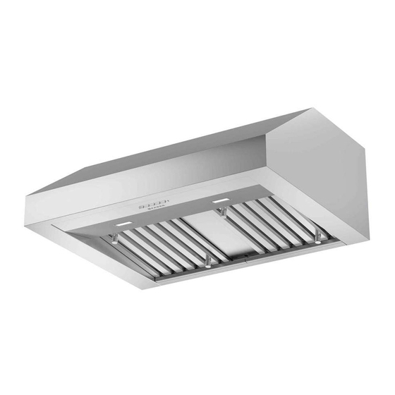
BREVA PRO 11
Installation instructions manual
Faber BREVA PRO 11 Installation Instructions Manual
Hide thumbs
1
Table Of Contents
2
3
4
5
6
7
8
9
10
11
12
13
14
15
16
17
18
19
20
21
22
23
24
25
26
27
28
29
30
31
32
33
34
35
36
37
38
page
of
38
Go
/
38
Contents
Table of Contents
Bookmarks
Table of Contents
Table of Contents
Important Safety Instructions
Range Hood Dimensions
Installation Height Requirements
Tools Needed
Parts
Venting Method
Mount the Motor into the Hood
Mount the SPACER (ONLY for BREVA 30)
Recirculation Instructions
Mounting on the Wall
Installation for Mounting under the Cabinet
Connecting House Power
Operating the Controls
CFM Adjustment < 295CFM
CFM Adjustment < 395CFM
Faber Cloud App
Remote Control
Cleaning Stainless Steel
Caring for Filters
Replacing the Activated Charcoal Filter
Replacing Bulbs
Wiring Diagram
Warranty
Advertisement
Quick Links
Download this manual
BREVA PRO 11
Installation Instructions
Use and Care Information
Instructions d'installation
Utilisez et d'entretien
Instrucciones de instalación
Información de uso y cuidado
BREV301SS600
BREV368SS600
Table of
Contents
Previous
Page
Next
Page
1
2
3
4
5
Advertisement
Table of Contents
Need help?
Do you have a question about the BREVA PRO 11 and is the answer not in the manual?
Ask a question
Questions and answers
Related Manuals for Faber BREVA PRO 11
Ventilation Hood Faber BREVA PRO BREV308SS600 Installation Instructions Manual
(60 pages)
Ventilation Hood Faber Inca Pro 38 Installation Instructions Manual
Power pack (13 pages)
Ventilation Hood Faber INCA PRO 30 RB Installation Instructions
Remote wall control (2 pages)
Ventilation Hood Faber INCA PRO 38 RB Installation Instructions Manual
Power pack (13 pages)
Ventilation Hood Faber 630003952 Instruction Manual
Power pack (15 pages)
Ventilation Hood Faber Pro Magnum Features & Dimensions
Faber product spec sheet (2 pages)
Ventilation Hood Faber PRO MAGNUMw Installation Instructions Manual
Wall mount canopy rangehood (8 pages)
Ventilation Hood Faber Pro Magnum User Instructions
Faber pro magnum wall mount canopy rangehood (15 pages)
Ventilation Hood Faber Pro Magnum Installation Instructions And Use & Care Manual
Faber wall mount canopy rangehood (7 pages)
Ventilation Hood Faber Inca Pro 30 Installation Instructions Manual
Power pack (13 pages)
Ventilation Hood Faber INCA PRO 30 Installation Instructions Manual
(15 pages)
Ventilation Hood Faber INCA PRO 18 Installation Instructions Manual
(84 pages)
Ventilation Hood Faber 36 Use And Care Manual / Installation Instructions
Wall mount canopy rangehood (15 pages)
Ventilation Hood Faber CYLINDRA 2 EV8 2EL XH890 Instruction Manual
Wall hood (84 pages)
Ventilation Hood Faber CUBIA GLOSS PLUS EV8 WH A60 Instruction Manual
(92 pages)
Ventilation Hood Faber CLASSICA PLUS CLPL36SSV2 Installation Instructions; Use And Care Information
(72 pages)
This manual is also suitable for:
Brev301ss600
Brev368ss600
Table of Contents
Print
Rename the bookmark
Delete bookmark?
Delete from my manuals?
Login
Sign In
OR
Sign in with Facebook
Sign in with Google
Upload manual
Upload from disk
Upload from URL


Need help?
Do you have a question about the BREVA PRO 11 and is the answer not in the manual?
Questions and answers