
Related Manuals for Pulsafeeder ELMA NEMA 4X


Summary of Contents for Pulsafeeder ELMA NEMA 4X
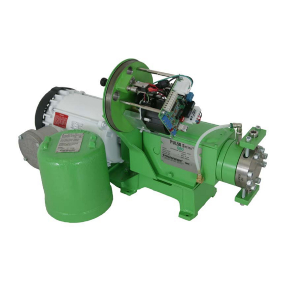
- Page 1 Installation, Operation & Maintenance Manual Stroke Length Controller ® ELMA CONTROLLER IOM-CTL-ELMA-2008 REV A...
-
Page 2: Table Of Contents
Table of Contents ATTENTION: R ..........1 ECALIBRATION OF THIS ELECTRONIC ACTUATOR IS REQUIRED OPERATIONAL NOTICE .......................... 1 1. M ........................2 ODEL REAKDOWN 2. I ............................. 3 NTRODUCTION General Description ........................ 3 Standard Features ........................3 Optional Features ........................4 3. -
Page 3: Attention: Recalibration Of This Electronic Actuator Is Required
ATTENTION Recalibration of this electronic actuator is required. 1. Although calibrated before leaving the factory, variations in input signals will require recalibration prior to start-up. Refer to the Calibration Section of this manual for complete instructions. 2. This actuator is equipped with signal protection circuitry. Recalibration will require changing the setting of the DIP switches which are a part of the protection system. -
Page 4: Model Code Breakdown
1. Model Code Breakdown Selecting an ELMA Model Number (e.g. BEMDA-BP) Pump Size Actuator Type Input Signal Action Power Requirement B = 680 E = NEMA Type 4X C = 10-50 mA D = Direct Action A = 115 V, 60 Hz C = 880 W = NEMA Type 7 D = 1-5 mA... -
Page 5: Introduction
injection in response to a pH signal for neutralization jobs, where the lower range signal requires reverse action. 2. Meter readout is for direct acting only. 3. Auto-manual includes auto-manual switch and manual potentiometer; switch is non- shorting type. 4. Option A and 8 in position 6 require Position 3 =X (no auto signal) 5. -
Page 6: Optional Features
10. The input and output signals are isolated from the power supply only 2.3 Optional Features 1. 3-15 PSI input signal @ 0 C.F.M. 2. Variable ratio control 3. Reverse acting control (e.g., 4 mA = 100%, 20 mA = 0%). 4. -
Page 7: Principals Of Operation
3. Principals of Operation 3.1 Basic Actuator The ELMA, (Electronic Lost Motion Actuator) is a simple control system composed of a position sensing device, an electronic circuit and a mechanical interface. The position sensor determines the actual stroke length, while the circuitry determines whether to increase, decrease or remain the same, and the mechanical interface actually performs the work of changing stroke length. -
Page 8: Features
TABLE 2 Signal Input Selection (Jumpers) Input Terminals 1-5 V 1 & 3 1-5 mA 1 & 2 4-20 mA 1 & 2 10-50 mA 1 & 2 Remote Auto Manual 3.2 Features Current Output Signal A 4-20 mA output signal is provided for remote monitoring of stroke length. This signal is generated by a voltage to current converter which is driven directly by the feedback potentiometer. -
Page 9: Installation
Split Ranging The split-ranging option provides full actuator response over one half the input signal range. Response can be set for the lower or upper half of the signal range and can be direct or reverse acting. 4. Installation 4.1 Check Model Number Check the ELMA model number breakdown for proper power supply connection. -
Page 10: Calibration
5. Calibration Before shipment, all actuators are calibrated to provide proper response to the input signal specified at the time of order. However, after installation, it is recommended that the unit be re-calibrated to compensate for any difference between factory and field conditions. Run the signal and accessory wiring using the second conduit fitting. - Page 11 c. With the voltmeter in the DC mode, measure and record the voltage across TB-1 and TB-3 at 0% and 100% process signal d. Remove the process signal from the board e. Manually adjust the micrometer hand knob to 0% stroke setting Locate the positive lead of the voltmeter to the wiper terminal (black lead) of the feedback potentiometer while the negative lead is on TB1-1.
-
Page 12: Deadband
5.3 Deadband See figures 3 & 4 Adjustment of the deadband determines how closely the comparator circuit will attempt to match the feedback signal to the input signal. It provides a “window” of acceptable voltage tolerances. Example If the deadband is too loose the comparator circuit is not as sensitive to signal change and may not fully adjust to the change of an input signal. -
Page 13: Ratio Control
d. Repeat steps b and c until 4-20 mA is output from the circuit when 0% and 100% is dialed in and/or meter reads minimum and maximum. 5.5 Ratio Control Due to highly tolerance components, no adjustment is necessary. 5.6 Pneumatic Input See figure 5 a. - Page 14 switch (see Fig. 3). During calibration the circuit may see under or over signals and therefore the protection feature must be turned off for proper adjustments to be made. Table 1 illustrates how the DIP switch settings relate to the different nodes. Re-calibration will require changing the setting of the dip switches to the open position (refer to Table 1, Function 1).
-
Page 16: Connection Diagram
5.8 Connection Diagram Since the hydraulic oil system is primed at the factory, priming the process system is all that should be necessary to produce flow. If the hydraulic system has inadvertently been dumped due to start up with restricted suction or discharge conditions or improper adjustments to compensator or bleed valves, repriming procedures under the maintenance section may have to be followed before pump calibration can begin. -
Page 17: Repairs
5.10 Repairs Potentiometer 1. Remove P3 connector from circuit board 2. Verify full potentiometer resistance of approximately 1,000 ohms between pins 2 and 3. 3. A needle type (analog) meter is recommended for checking potentiometer operation. As the potentiometer gear is turned counter clockwise (as seen from the gear end), the resistance between pins 1 and 2 should vary uniformly from zero to approximately 1,000 ohms. - Page 18 Machining Gearbox 1. With table indicated perpendicular to machining head clamp gearbox to table with head end down. 2. With indicator, locate machining head to center od adjustment shaft hold in gearbox 3. Bore adjustment shaft hold, to 0.625 +000/0.001” diameter 4.
- Page 19 Assembly of ELMA Control 1. Reinstall crosshead, pump head and reagent head assembly 2. Holding rear mechanical stop against bushing, push adjustment shaft extension forward until it hits the stop. Slide nylon washer, over shaft extension. Slide timing gear over shaft extension forward to gearbox. Secure timing gear in place with 2 #8-32 setscrews spaced 90 degrees apart.
- Page 20 6. Place reference marker on timing gear and gearbox. (Felt marker works best) 7. Slide rear mechanical stop back against bushing and secure in place with setscrews. 8. Pull timing gear and shaft extension from gearbox. (Check that nylon washer remains next to timing gear) 9.
-
Page 21: Specifications
6. Specifications NEMA Type 4X Actuator Enclosure • 0-100% Stroke Length Indicator at pump • 115 V, 60 Hz or 220 V, 50 Hz, 1 phase AC supply • Signal Ranges a. 4-20 mA dc @ 250 ohm impedance b. 1-5 V dc greater than 270,000 ohm c. -
Page 22: Nema Type 4X Cross Section
NEMA Type 4X Cross Section... -
Page 23: Nema Type 4X Exploded Isometric
NEMA Type 4X Exploded Isometric... -
Page 24: Nema Type 7 Cross Section
NEMA Type 7 Cross Section... -
Page 25: Nema Type 7 Exploded Isometric
NEMA Type 7 Exploded Isometric... - Page 27 Installation, Operation & Maintenance Instruction Stroke Length Controller ® ELMA CONTROLLER Bulletin #: IOM-CTL-AE-2008 REV A Stroke Length Controller A unit of IDEX Corporation 2883 Brighton Henrietta Town Line Road Rochester NY 14623 +1 (585) 292-8000 www.pulsa.com pulsa@idexcorp.com...
Need help?
Do you have a question about the ELMA NEMA 4X and is the answer not in the manual?
Questions and answers