
Related Manuals for Pulsafeeder PULSAmatic 7120


Summary of Contents for Pulsafeeder PULSAmatic 7120
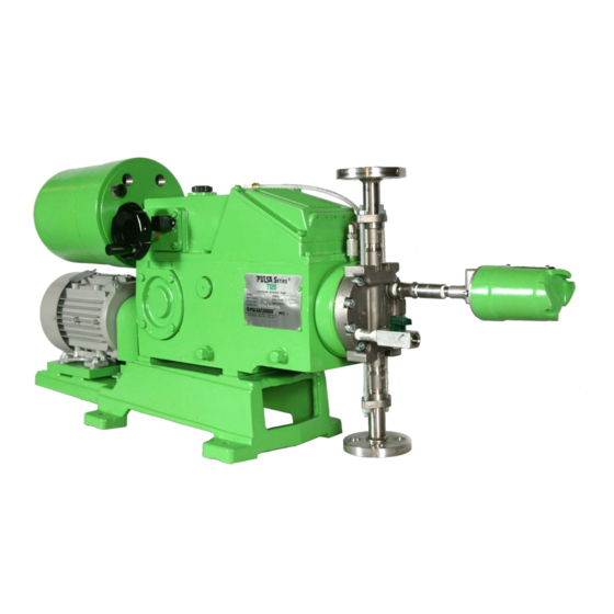
- Page 1 Installation, Operation & Maintenance Instruction Stroke Length Controller ® PULSAmatic CONTROLLER Bulletin #: IOM-CTL-AE-2006 REV A...
- Page 2 Any modifications or out-of-warranty repairs will be subject to bench fees and costs associated with replacement parts. In addition, Pulsafeeder guarantees its PULSA Series drive assemblies for a period of two years from the date of shipment. All other material and workmanship are fully covered for a period of one year.
-
Page 3: Table Of Contents
Table of Contents 1. I ............................. 1 NTRODUCTION General Description ........................ 1 Options ............................. 3 Input Signals ..........................3 Control Modes ......................... 4 Current Output Signals ......................4 2. E ........................4 QUIPMENT NSPECTION 3. P ..........................4 ROCEDURAL OTES 4. -
Page 4: Introduction
1. Introduction General Description The PULSAmatic actuator converts reciprocating motion of the pump into rotary motion to turn the pump’s stroke adjustment screw. By selectively engaging either of the two oppositely oriented, one-way clutches, one of two corresponding nuts hat ordinarily rotate freely on a “diamond”... -
Page 6: Options
Options The PULSAmatic actuator is configured at the factory for a variety of options, both singly and in various combinations. The appropriate wiring diagrams external to the circuit board are included with each pump shipment. Input Signals Standard signals are: 1-5 mA DC @ 2000 ohm Impedance 4-20 mA DC @ 470 ohm Impedance 10-50 mA DC @ 180 ohm Impedance... -
Page 7: Control Modes
Control Modes Ratio Control- When ratio control is applied, the range of stroke adjustment is proportionally reduced to a level equal to the ratio setting. For example, at a ratio setting of 60%, the full span of the input signal commands the pump to operate between zero and 60% of full stroke rather than over the full range of the stroke. -
Page 8: Installation
4. INSTALLATION Wiring Up (Refer to any special wiring diagrams and installation drawings supplied by Pulsafeeder). AC power lines should be routed to the actuator via a separate conduit from the control signal and any optional accessory wiring. A separate switched and protected circuit is recommended for the actuator power supply. -
Page 9: Start Up
specifications required in support of UL listing. They must be installed, wired, operated, and maintained in accordance with local electrical codes. CAUTION: To help protect the integrated circuits in the servo amplifier, always energize AC power prior to connecting the signal leads. Start Up Ever actuator is adjusted and calibrated at the factory. -
Page 10: Circuit Board Calibration
For example, if a pump is operating at 50% stroke in response to a 50% input signal, the signal must typically increase to 51% or decrease to 49% before the actuator does not respond, or is “dead”, is called “deadband”. If deadband is too narrow, the actuator will frequently make slight adjustments in response o small signal variations. - Page 11 10. The above adjustments are interactive. It may be necessary to repeat steps (2) through (5) several times until the voltages stabilize. This completes coarse adjustment. Without Ratio Control – Fine Adjustment 11. With the override switch still in the “out” or manual position start the pump. 12.
-
Page 12: Meter Readout Calibration
12. The above adjustments are interactive. It may be necessary to repeat steps (8) through (12) several times until the voltages stabilize. This completes coarse adjustment With Ratio Control (Optional Feature) – Fine Adjustment 13. With the override switch still in the “out” or manual position start the pump. 14. -
Page 13: Repairs
This procedure can be performed with the pump on-line and operating, in the manual (handwheel) control mode, with the override switch in the “out” position. 1. All voltages in this procedure are DC and are measured between TB2-2 (positive) and TB2-1 (common). -
Page 14: Zero Alignment
removed from pins 5 and 3 should vary uniformly from zero to approximately 1000 ohms. As the potentiometer gear is turned clockwise, the resistance should vary uniformly from approximately 1000 ohms to zero. 4. If the extreme readings vary significantly from zero and 1000 ohms respectively or if the resistance variation with rotation is not smooth at any point, the potentiometer should be replaced. -
Page 15: Brake Air Gap
8. Replace the cover screws. 9. With the handwheel fully clockwise, the stroke position indicator show read (000). If not, remove the handwheel assembly form the cover assembly, turn to the (000) setting and replace. 10. Align the potentiometer as described under “Repairs”. 11. -
Page 16: Jammed Slider Block
2. If either brake drags without being energized and the gap is less than 10 mils, equally shim all three spacer sleeves, Items #608, to increase the air gap to the specified range. Refer to Figures 6 and 7. Item 607 denotes shim location on the illustrations, but as a spare part. - Page 17 5. Remove the rear connecting rod cotter pin (#545) and wrist pin (#544). 6. Remove the housing pivot pins (#547). Models 7120 and 7440 Remove the retainer set screws (#546) located directly above the housing pins in the opt surface of the gearbox. NOTE: If slight heat is applied to the pivot pins to loosen paint, or sealant, ensure that no cleaning or combustible fumes or materials are present.
- Page 18 On explosion proof models, the diamond shaft is retained in the PULSAmatic unit and does not come out so the drive shaft assembly must be fed into the housing cap as the cover assembly is lowered onto the pump. The slotted nut (#535) should be adjusted as above.
-
Page 19: Troubleshooting
9. Troubleshooting PROBLEM PROBABLE CAUSE 1. No AC power to actuator. 2. Pump not running. 3. Override switch not pushed in. 4. Control signal off, incorrect, or of inverted polarity. 5. Ratio control (if so equipped) set at or very near zero percent. 6. - Page 20 Figure 5 AP00229...
- Page 21 MODEL 7120/7440 AE HOUSING ASSEMBLY PULSAMATIC CONTROL (Reference Figure 5) ITEM PART NAME QUANTITY Housing Housing Block Connecting Rod-Front Adjustment Screw Miter Gear Housing Cap Assembly Cap Screw Washer Washer Housing Assembly: Consists of all the above components pre- assembled...
- Page 22 MODEL 7660/8480 AE HOUSING ASSEMBLY PULSAMATIC CONTROL (Reference Figure 5) ITEM PART NAME QUANTITY Housing Housing Block Connecting Rod-Front Adjustment Screw Miter Gear Housing Cap Assembly Cap Screw Washer Washer Housing Assembly: Consists of all the above components pre- assembled...
- Page 23 Figure 6 Standard NEMA 4 ENCLOSURE...
- Page 24 MODEL 7120/7440/7660/8480 NEMA 4 ACTUATOR ASSEMBLY PULSAMATIC CONTROL AP00332 (Reference Figure 6)
- Page 25 AP00333 Figure 7 EXPLOSION PROOF ENCLOSURE AP00334...
- Page 26 MODEL 7120/7440/7660/8480 NEMA 7 ACTUATOR ASSEMBLY PULSAMATIC CONTROL (Reference Figure 7) AP00335...
- Page 27 Figure 8 MODELS 7120 AND 7440 AP00330...
- Page 28 MODEL 7120/7440 -AE CONTROL ASSEMBLY PULSAMATIC CONTROL (Reference Figure 8) ITEM PART NAME QUANTITY Handwheel Set Screw Counter Round Head Screw Counter Gasket Bushing Set Screw Mounting Plate Cap Screw Gasket Gear 48T Gear 16T Set Screw Gear 22T Spacer Washer Washer Cap Screw...
- Page 29 526B Cover Gasket Dip Stick Assembly 529A Breather Cover 529B Diaphragm Fillister Head Screw Drive Shaft Assembly Bushing Miter Gear Washer Slotted Nut Actuator Assembly Spacer Cotter Pin Housing Assembly Warning Plate Drive Screw Cap Screw Cotter Pin Set Screw Housing Bolt o-Ring Set Screw...
- Page 30 Figure 9 MODELS 7660 AND 8480...
- Page 31 MODEL 7660/8480 -AE CONTROL ASSEMBLY PULSAMATIC CONTROL (Reference Figure 9) ITEM PART NAME QUANTITY Handwheel Set Screw Counter Round Head Screw Counter Gasket Bushing Set Screw Mounting Plate Cap Screw Gasket Gear 48T Gear 16T Set Screw Gear 22T Spacer Washer Washer Cap Screw...
- Page 32 Dip Stick Assembly 528A Front Cover 528B Diaphragm 529A Cover Plate 529B Gasket Fillister Head Screw Drive Shaft Assembly Bushing Miter Gear Washer Slotted Nut Actuator Assembly Spacer Cotter Pin Housing Assembly Warning Plate Drive Screw Cap Screw Cotter Pin Hex Head Bolt Housing Bolt Gasket...
- Page 34 ® PULSAmatic CONTROLLER Bulletin #: IOM-CTL-AE-2006 REV A Stroke Length Controller A unit of IDEX Corporation 2883 Brighton Henrietta Town Line Road Rochester NY 14623 +1 (585) 292-8000 www.pulsa.com pulsa@idexcorp.com...
Need help?
Do you have a question about the PULSAmatic 7120 and is the answer not in the manual?
Questions and answers