
Related Manuals for Pulsafeeder MicroVision


Summary of Contents for Pulsafeeder MicroVision
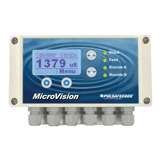
- Page 1 MicroVision MICROPROCESSOR – BASED WATER TREATMENT CONTROLLER Installation Operation Manual 72-910-16 Rev. N Page 1 of 43...
-
Page 2: Table Of Contents
Table of Contents INTRODUCTION ........................4 MICROVISION FEATURES ....................... 4 Toroidal Probe ..........................4 Output Relays ..........................5 Drum Levels ..........................5 Flow Switch ..........................5 4-20mA Output ..........................6 Water Meter ..........................6 Alarm Relay ..........................6 INSTALLATION ......................... 7 Opening The Enclosure ......................... - Page 3 7.20 Conductivity Menu ........................25 7.21 Inhibitor Menu ..........................26 7.22 Inhibitor - Inhibitor Feed Mode Menu ..................27 Inhibitor - Inhibitor Feed Mode – Pulse Timer Menu ..............27 7.23 Inhibitor - Inhibitor Feed Mode – % Post Blowdown Menu ............28 7.24 Inhibitor –...
-
Page 4: Introduction
TDS, is bled resulting in fresh make-up water being added, reducing the concentration of TDS in the cooling system. In addition to the bleed relay, MicroVision has three (3) other onboard control relays assigned as follows:... -
Page 5: Output Relays
2.4 Flow Switch MicroVision has a dry contact flow switch input that will de-activate all of the control output relays upon a no-flow indication. An Alarm condition will be indicated and “No Flow” will be displayed. This input is active closed: Open = no flow;... -
Page 6: 4-20Ma Output
4-20mA output. 2.6 Water Meter MicroVision has a dedicated water meter that is capable of reading a dry contact or Hall effect type water meter. Through programming this input can be used to feed inhibitor as well as totalizing water consumption. -
Page 7: Installation
3. INSTALLATION Input power cord must be disconnected from power source prior to opening the product’s enclosure. 3.1 Opening The Enclosure Loosen the four (4) screws on the front of the controller and carefully swing the top of the case to the right (Fig. 2). HINGE DRUM LEVEL 4-20mA... -
Page 8: Location
3.2 Location Select a mounting location convenient to grounded electrical and plumbing connections. It is recommended that you mount the controller on a wall or other vertical surface with adequate lighting at a comfortable level. A mounting-hole template is supplied with your controller. Installation should comply with all national, state, and local codes. -
Page 9: Sensor Installation
recommendation. Panel mount hardware should support 25lbs. For hole locations, see the mounting hole pattern (Fig. 9) found on the page 39 of manual. 3.4 Sensor Installation The controller is supplied with a temperature compensated toroidal conductivity sensor (probe). Install the sensor at some point in your process where chemical and water are thoroughly mixed. -
Page 10: Typical Installation
Bleed DISPLAY Feed SCREEN Biocide A Biocide B MicroVision Fig. 5 4. IMPORTANT SYMBOL INFORMATION Warning indicates a condition that could cause damage to both the equipment and the personnel operating it. Pay close attention to any warning. Primary Supply Ground must be connected to earth ground for safe operation of your controller. -
Page 11: Electrical Wiring
It should be in close proximity to the unit and easily reached by the user. The MicroVision electronic input circuitry is fuse protected on both the hot and neutral inputs using a replaceable five amp fuse (Fig .6). -
Page 12: Relay Board Connections
5.1 RELAY BOARD CONNECTIONS MOTORIZED BALL VALVE PUMP (4-WIRE) (3-WIRE) (RETURN / NEUTRAL) (RETURN / NEUTRAL) (EARTH / CHASSIS GROUND) (EARTH / CHASSIS GROUND) (NORMALLY / OPEN) (NORMALLY / OPEN) (NORMALLY / CLOSED) AC POWER IN INHIB BIO A BIO B SUPPLY BLEED INHIB... -
Page 13: Low Voltage Connections
for conduit power and load connections. Supply (input) power is connected via PL5 located on the relay board (Fig. 6). The top part of this terminal block is removable to allow for easy access to the connector’s three (3) screws. Make sure that all conduit connections are water tight. -
Page 14: Flow Switch Input
Low voltage signal wires, e.g., water meter, must be run separate from AC power lines. These connections will be covered in the Low Voltage section of the manual. 5.4 Flow Switch Input It is recommended that a flow switch or auxiliary dry contact be used to make outputs inoperative when the cooling tower is shut down. -
Page 15: Front Panel Description
DISPLAY Feed SCREEN Biocide A Biocide B MicroVision Fig. 8 6.1 Keypad Operation UP/DOWN - Dual function keys. Used to move the select (highlighted) box and to increase and decrease values. Soft keys used for various functions depending on currently displayed screen. -
Page 16: Controller Programming
7. CONTROLLER PROGRAMMING 7.1 Menu Tree HOME ENTER SCREEN PASSWORD STATUS MENU CONFIGURE SETTINGS DATE & TIME CONDUCTIVITY HOA OUTPUTS SETPOINT LANGUAGE LIMIT TIMER WATER METER DIFFERENTIAL DRUM LEVELS PROBE CAL ALARM SETP'T DISP.DAMP 4-20 OUTPUT RISE/FALL CONTRAST INHIBITOR INH FEED MODE PASSWORD BIO TRACKING TROUBLESHOOT... -
Page 17: Menu Navigation
Microvision. If an alarm condition occurs an alarm message will flash on the screen. The four LED’s to the right of the display will also flash indicating an alarm has occurred. The Microvision will return to this screen home screen if no buttons are pressed for five minutes after entering a menu. -
Page 18: Status Screen
7.5 Status Screen Home Screen Water Meter: 0000000000 Bleed: 123.4 Inhib 123.4 BioA: 123.4 BioB 123.4 Probe Temp: 24.4 C Last Error: Low Flow Back | Reset This screen shows the real-time data relating to the controller. This screen can be used to log the amount of time a particular output was energized since it was last reset. -
Page 19: Date/Time Menu
Date/Time – Set the current date, date format, time, and time format. HOA Outputs – Manually control the four output relays. Water Meter – Set the water meter type and volume. Language – Change the controller displayed language. Drum Levels – Set the control output mode when a drum level goes low. Display Dampener –... -
Page 20: Water Meter Menu
Biocide A – Force the biocide A control output on or off. Biocide B – Force the biocide B control output on or off. Auto – Return the control output to normal operation. On 5 Min – Energize the control output for five minutes. Off –... -
Page 21: Display Dampener
7.13 Rising/Falling Setpoint Option From the Rise/Fall setpoint option you select which direction the conductivity will tend to go in the process being controlled. If the Microvision is controlling a cooling tower use the Rising setpoint option. 72-910-16 Rev. N... -
Page 22: Display Contrast Setting
Home Screen Configure Rising Setp’t Falling Setp’t Rise/Fall Back | Select Rising Setpoint – Select this option if a cooling tower is being controlled. Falling Setpoint – Select this option if the conductivity tend to fall as a result of the process. -
Page 23: Troubleshoot Screen
Please have the controller in front of you when you place the call. 7.16 Troubleshoot Screen From the Troubleshot Screen you can view the Microvision control inputs in real-time. This is a great tool for checking the correct operation of sensors that are attached to the controller. -
Page 24: Factory Reset Function
7.18 Factory Reset Function From the Factory Reset Function screen you can force the controller to reset all of its internal parameter to the factory default values. Home Screen Configure Factory Reset To RESET Are you sure! Enter 9999 Factory Rst 0000 Cancel | OK Cancel | OK... -
Page 25: Settings Menu
7.19 Settings Menu From the Settings menu you access the conductivity, inhibitor feed, and dual biocide feed parameter sections. Home Screen Conductivity Inhibitor Settings Biocide A Biocide B Back | Select Conductivity – Set the conductivity setpoint, differential, probe calibration, alarms, and 4-20ma output parameters. -
Page 26: Inhibitor Menu
Limit Timer – Set this value to the maximum amount of time the bleed output can stay energized before a Bleed Limit alarm is reported. The limit time setting only reports the alarm and does NOT turn off the bleed output. If the next bleed cycle completes without an alarm the alarm will clear itself. -
Page 27: Inhibitor - Inhibitor Feed Mode Menu
7.22 Inhibitor - Inhibitor Feed Mode Menu From this menu pick the mode that the inhibitor feed will follow. Home Screen Settings Pulse Timer Inhibitor Limit Timer Cycle Timer Inh Feed Mode % Post Bl’d Back | Select Pulse Timer – See the menu for this function in the following section. Limit Timer –... -
Page 28: Inhibitor - Inhibitor Feed Mode - % Post Blowdown Menu
Accumulator Set – Set this value to the amount of water that needs to accumulate prior to an inhibitor feed. The units will be in gallons or liters depending on what you set the water meter units to. Accumulator Count – This is the current running count of the inhibitor water meter accumulator. -
Page 29: Biocide A Or B Menu
Skip – Choose this option if you want the inhibitor to skip a feed cycle if a biocide happens to be feeding. Pause – Choose this option if you want the inhibitor feed cycle to pause or delay until the biocide feed cycle is complete. When the biocide feed cycle is complete the inhibitor will then feed. -
Page 30: Biocide A Or B - Days/Weeks Menu
7.27 Biocide A or B – Days/Weeks Menu From this menu configure the days and weeks the biocide will feed. Any combination of days and/or weeks is acceptable for each biocide feed timer. Home Screen Settings Biocide X Days/Weeks ALL | SUN| MON| TUE ALL | EVN| ODD| 1ST WED| THU| FRI | SAT 2ND | 3RD| 4TH |... -
Page 31: Probe Calibration
8. Probe Calibration Because there are no metal electrodes to foul no re-calibration is required of this toroidal probe on a regular basis. However, you may want to calibrate the probe initially to get a base-line reading for future reference. There are two methods of probe calibration that can be used to calibrate this probe. - Page 32 Standard Solution Calibration – This calibration technique is typically used when the probe is removed from the process flow or prior to probe installation. Use a standard solution that is near the conductivity setpoint you plan on setting the controller Step 1 –...
-
Page 33: Factory Defaults
9. Factory Defaults Parameter Default Configuration MM/DD/YY Date Format 12hr Clock Time Format Dry Contact Water Meter Type Water Meter Pulse Volume Gallons Water Meter Units Pumps Run Drum Levels 1 Second Display Dampener ... -
Page 34: Troubleshooting Guide
10. TROUBLESHOOTING GUIDE Symptom Probable Cause Possible Solution Controller does not power No power supplied to controller. Insure that correct voltage is supplied to controller. Check circuit breaker supplying power to the controller. Fuse is blown. check/replace fuses F1-F3 (see Figure F6, Page 12) Ribbon cable. - Page 35 Drum level switch stuck. Clean switch sensor mechanicals. Controller displays "Inhib Programmed inhibitor feed limit Adjust limit timer value to longer duration (See Page Limit" alarm message. timer set too short. 26). Clogged bleed valve or drain. Clean valve or drain. Faulty bleed valve.
-
Page 36: Maintenance
11. MAINTENANCE The only recommended maintenance required on your controller is periodic inspection of the conductivity sensor every 6 months. It is recommended that you establish a regular maintenance schedule designed to meet the needs of your particular application. All other service should be performed by factory authorized personnel only. - Page 37 Probe Maximum temperature 122° F (50°C) Temperature compensation 32°F – 122°F (0° – 50°C) range Maximum pressure 125 PSI (8,6 BAR) Probe type Toroidal Maximum cable length 100 Feet (30,5 Meters) Materials of construction Polypropylene ½” Standard thread -Excludes Tee Thread size and Reducer 1.5”...
-
Page 38: Glossary
13. GLOSSARY Alarm Relay – an electric circuit when triggered by a predetermined signal will activate an externally connected alarm Analog – a continuous signal (4-20mA) that can be used to represent a physical variable, e.g., conductivity Biocide – an agent used to control the growth of algae and other organic substances Bleed –... - Page 39 Inputs – receptacles or hock-ups for signals delivered to the controller Interval – the amount of time between bleed events Isolated Input – an input (analog or digital) that is electrically isolated from main power supply and its ground (ISO) Isolation Valves – general term that refers to valves in the system used to isolate various components of the system from the main flow Jumper –...
- Page 40 System Overfeed – usually a malfunction condition where a feed pump fails in the Run (ON) condition System Parameters – see program parameters TDS – abbreviation for Total Dissolved Solids, measured in terms of electrical conductivity (S/CM) Temperature Compensation – displays conductivity as if measured at 77°F (25°C) Toroidal Conductivity –...
-
Page 41: Mounting Hole Pattern (Footprint)
14. MOUNTING HOLE PATTERN (Footprint) Fig. 9 72-910-16 Rev. N Page 41 of 43... -
Page 42: Factory Service Policy
All returns require a Return Authorization number to be issued by Pulsafeeder. Parts purchased to correct a warranty issue may be credited after an examination of original parts by Pulsafeeder. Warranty parts returned as defective which test good will be sent back freight collect. - Page 43 European Union (EU) Pulsafeeder, Inc. PULSAFEEDER-Europe 27101 Airport Rd. Via Kennedy, 12-20090 Punta Gorda, FL 33982 Segrate—Milano– Italy (941) 575-3800 www.pulsa.com 72-910-16 Rev. N Page 43 of 43...
Need help?
Do you have a question about the MicroVision and is the answer not in the manual?
Questions and answers