
Related Manuals for Aeson Power TL-LFP Series

Summary of Contents for Aeson Power TL-LFP Series
- Page 1 Installation and Operation Manual kW h 48Vdc 4.8 to 38.4 Battery Energy Storage Unit Page 1...
-
Page 2: Table Of Contents
Contents Part 1 - Safety & Warning ..........................3 Part 2 - Product Introduction ..........................4 2.1 - Overview .............................. 4 2.2 - Working Principle ..........................4 2.3- Battery Management System (BMS)....................5 2.4- Applications ............................8 2.5- Battery Model Name ..........................8 2.6 - Electric Performance ........................... -
Page 3: Part 1 - Safety & Warning
Part 1 - Safety & Warning The TL-LFP series LiFePO battery system installation, operation and maintenance should follow important recommendations in this manual: ▪ The equipment must be installed by a licensed electrician. ▪ Battery maintenance should be carried out by experienced professionals, fully trained in safety measures and aware of the risks and dangers presented by the battery. -
Page 4: Part 2 - Product Introduction
Part 2 - Product Introduction 2.1 - Overview TL Series Lithium-Ion batteries is a range of batteries packed with advanced LiFePO4 technology and possessing intelligent integrated BMS. The TL battery range has the advantages of: - Long cycle life; - Light weight; - Small size;... -
Page 5: Battery Management System (Bms)
2.3- Battery Management System (BMS) The TL–LFP Series battery modules are equipped with technologically advanced Integrated Smart BMS. Features of the BMS are described below: Overcharge Protection When the voltage of any cell comprising a module, is greater than the Overvoltage setting, and the duration of the Overvoltage status exceeds the set time delay of the overcharge protection, the OV Protection plate closes the MOSFET on the charging circuit and the charging is interrupted. - Page 6 Heat Management The thermal management BMS function can be described as follows: if the battery temperature exceeds the set normal working parameters (higher or lower), the alarm will be raised - red ALM light will come on and the battery will be disconnected. When the temperature of the battery, after having been disconnected due to over-temperature condition, drops to the set value of normal working parameters, the BMS reconnects the battery to the load / charge, and the red ALM light is off.
- Page 7 Sleep and Wake Function Sleep condition Wake-up condition Remark In the idle state (no charge, discharge, no Charge and discharge, The battery with a communication), the lowest voltage of any communication, reset soft switch can be cell is lower than the set sleep voltage (can be button, soft switch wakened up set), after 30 minutes, enter normal sleep.
-
Page 8: Applications
2.4- Applications ▪ Telecommunication ▪ Indoor distribution system ▪ Energy storage system 2.5- Battery Model Name 2.6 - Electric Performance Table 2.1 - Battery Model & Electric Performance Page 8... -
Page 9: Structure And Mechanical Performance
2.7 -Structure and Mechanical Performance Table2.2 - Mechanical Performance Page 9... -
Page 10: Appearance & Mechanical Drawing
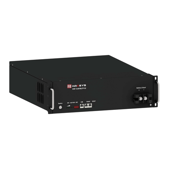
2.8 -Appearance & Mechanical Drawing Page 10... -
Page 11: Part 3 - Technical Characteristics
Part 3 - Technical Characteristics 3.1 - Discharge Performance Fig. 3.1 - Constant Current Discharge Curve of TL-LFP Series @25℃ Fig. 3.1 - Discharge Curve of different temperature of TL-LFP Series@1.0C Page 11... -
Page 12: Charge Performance
3.2 - Charge Performance Fig. 3.3 - Charge Characteristic with Various Current Limitation of TL-LFP Series 3.3 - Constant Current Discharge Table Constant Current Discharge Table(25℃) Table 3.1 Page 12... -
Page 13: Part 4 - Operation & Maintenance
4.1 - Requirements for Operation Environment 4.2 - Parameter Settings of Power Plant Lead-acid batteries can be replaced by lithium battery of TL-LFP series if power is matched. Table 4.2 Parameter settings of power plant for lithium-ion battery. Table 4.2 - Parameter Settings of Power Plant for TL48V-LFP Series Batteries... -
Page 14: Charge/Discharge Modes And Conditions
4.3 - Charge/Discharge Modes and Conditions Page 14... -
Page 15: Layout Of Front Panel
4.4 - Layout of Front Panel 1 2 3 4 5 Table 4.5 - Instruction for Layout of Front Panel Marks Functions Detailed Information There are four green LED lights in front panel indicating SOC.SOC is short for Indicators for state of charge. -
Page 16: Shipment
It is adopting RS485 series port communication pattern to upload data. Cascading Communication of modules connected in parallel (Slave PACKs) is available RS485 communication through RS 485. Data of slave PACKs will be transmitted to Master PACK. port Protocol for RS232 communication is shown in Annexed Table 3.2 RESET Reset button... - Page 17 Removal of Rack from shipping Pallet 1) Rack with no batteries installed. • Rack transport mounting screws will need to be removed before final positioning. • Remove covers in the bottom of the rack as shown in the picture as shown below to gain access to the transportation bolts and plates.
- Page 18 The transport bolts are M12, use shifters, spanners or sockets to remove these bolts to free the rack from the pallet. Once transportation Screws have been removed from the Rack, it is safe to remove the rack from the pallet, please note to remove the rack from the pallet it is recommended the use of more than 2 people to safely lift the rack from the pallet and on to the floor.
- Page 19 Below are recommended furniture remover dollies to lift and move the rack into the final location. • Insert battery module into rack, using the two fixing handles of each battery module and use the M6 screws to fix in to position. •...
- Page 20 Installation of Battery Modules if supplied under option 2 1) Rack with batteries installed. • Rack transport mounting screws will need to be removed before final positioning. • Remove covers in the bottom of the rack as shown in the picture as shown below to gain access to the transportation bolts and plates.
- Page 21 The transport bolts are M12, use shifters, spanners, or sockets to remove these bolts to free the rack from the pallet. Remove transport nuts & bolts. Page 21...
- Page 22 The picture above shows that the pallet is required to be cut to remove the rack from the pallet due to the weight. Cut the slats our as shown on the picture, this will have to be done on both sides of the pallet so that furniture lifters can be inserted underneath the rack for removal.
- Page 23 Below are recommended furniture remover dollies to lift and move the rack into the final location. Once the rack is on the ground a pallet jack or furniture remover dollies can be used to move the rack to its final location. •...
- Page 24 4) Power on for battery module • When installation is accomplished, battery modules are in dormant state. Once powered up or turned on the battery module will go into normal running status, and discharge/charge state will be available. • Parameter settings for lithium battery modules in power plant are shown in Table 4.2. 5) RS232/RS485 connection •...
-
Page 25: Storage
4.7 - Storage The battery storage shall be in a clean and dry ventilation room at the temperature of 0~40°C and shall be kept away from fire or heat and avoid touching corrosion elements. The batteries shall charged every 8 or 12 months (0 ~ 30℃ - 12month, 30 ~ 40℃ - 8month) during storage. 4.8 - Maintenance •... -
Page 26: Annex 1 - Instructions For Led Flicker
Different flash status of LED indicators represents corresponding running status or alarms. Detailed information is shown Annex 1. Annex 1 - Instructions for LED Flicker Annex Table 1.1 - SOC LED Indicators Description ● ● ● ● ☼ ☼ ☼ ☼... - Page 27 Alarm light Over According to the SOC goes temperature, Flash after a few under-temper Flash 1 Discharge seconds ature, over-current protection Flash Charge / Discharge Flash 1/Normall The fault According to the SOC /Standby y on/Flash LED Flash State Light Extinguish Flash1 0.25S...
-
Page 28: Annex 3 - Communication Protocol For Rs232 And Rs485
PACK 11 001010 Slave PACK PACK 12 001011 Slave PACK PACK 13 001100 Slave PACK PACK 14 001101 Slave PACK PACK 15 001110 Slave PACK PACK 16 001111 Slave PACK Annex 3 - Communication Protocol for RS232 and RS485 There is one RS232 port in front panel for up-link communication between battery module and upper computer, and one or two RS485 ports in front panel for cascade communication for battery modules connected in parallel. -
Page 29: Annex 4 - Rack Tech Data
Annex 4 – Rack Tech Data Model AESON 28.8kW Rack System Dimensions 45RU 2,210mm (H) x 640mm (W) x 800mm (D) Colour Powder Coated Black with Glass Door with Vented Rear Door Floor Mounting Feet Adjustable Number of Batteries VHR TL48100LFP-3U Battery Type Connection Rear Bus Bars with holes for M10 Bolts 700A (8nm) - Page 30 7 x 100A 10kA DC Breakers Internal Cabling 2 x 25mm Sq Black DC Cabling Cable Entry Top or Rear IP Rating IP20 466 Kg’s Weight Please note in efforts to enhance this product this specification is subject to change at any time without notice.
-
Page 31: Annex 5 - Installation Recommendations
Annex 5 – Installation Recommendations To AS:5139/2019 Installation Section Pic 1 • The wall needs to be fire rated to AS1530.1 behind the Aeson Power battery cabinet, or to be hard surface. • Non-combustible material must protrude 600mm past each side and 900mm above the Aeson Power battery cabinet. - Page 32 • There must be 600mm unobstructed access each side of Aeson Power battery cabinet. • There must be 600mm clearance unobstructed access on working side of the Aeson Power battery cabinet when voltage is DVC-A +>4Cal/cm3. • There must be 900mm clearance unobstructed access in front (working Side) of the Aeson Power battery cabinet when voltage is greater than DVC-A +>4Cal/cm3.
Need help?
Do you have a question about the TL-LFP Series and is the answer not in the manual?
Questions and answers