
Subscribe to Our Youtube Channel
Related Manuals for Spirit CRS800S


Summary of Contents for Spirit CRS800S
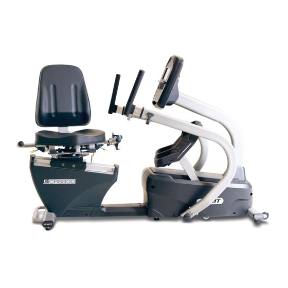
- Page 1 Owner’s Manual Model No. 16807058000 CRS800S - Assembly - Operation - Adjustments - Parts - Warranty CAUTION: Read and understand this manual before operating unit Retain For Future Reference...
-
Page 2: Table Of Contents
TABLE OF CONTENTS Product Registration ................2 Safety Precautions ................... 4 Important Safety Instructions..............5 Important Operation Instructions .............. 6 Assembly Instructions ................8 Operation of the Console ............... 15 Using the Heart Rate Transmitter ............24 General Maintenance ................25 Exploded View Diagram ................. -
Page 3: Product Registration
CONGRATULATIONS ON YOUR NEW RECUMBENT STEPPER AND WELCOME TO THE SPIRIT FAMILY! Thank you for your purchase of this quality recumbent stepper from Dyaco Canada Inc. Your new stepper was manufactured by one of the leading fitness manufacturers in the world and is backed by one of the most comprehensive warranties available. - Page 4 BEFORE YOU BEGIN Thank you for choosing the SPIRIT CRS800S Recumbent Stepper. We take great pride in producing this quality product and hope it will provide many hours of quality exercise to make you feel better, look better, and enjoy life to its fullest. It's a proven fact that a regular exercise program can improve your physical and mental health.
-
Page 5: Safety Precautions
SAFETY PRECAUTIONS IMPORTANT SAFETY INFORMATION THIS UNIT IS INTENDED FOR HOUSEHOLD USE ONLY READ ALL INSTRUCTIONS BEFORE USING THIS STEPPER CAUTION: Before starting any exercise program, it is recommended that you consult your physician. Thank you for purchasing our product. Even though we go to great efforts to ensure the quality of each product we produce, occasional errors and/or omissions do occur. -
Page 6: Important Safety Instructions
IMPORTANT SAFETY INSTRUCTIONS WARNING - Read all instructions before using this equipment. DANGER - To reduce the risk of electric shock: Always unplug this exercise equipment from the electrical outlet immediately after using and before cleaning. WARNING - To reduce the risk of burns, fire, electric shock, or injury to persons, install the Stepper on a flat level surface with access to a 120-volt,15-amp grounded outlet with only the Stepper plugged into the circuit. -
Page 7: Important Operation Instructions
IMPORTANT OPERATION INSTRUCTIONS NEVER operate this Recumbent Stepper without reading and completely understanding the results of any operational change you request from the console. Understand that changes in resistance do not occur immediately. Set your desired resistance on the computer console and release the adjustment key. The computer will obey the command gradually. - Page 8 WARNING DECAL REPLACEMENT The decal shown below has been placed on the stepper. If the decal is missing or illegible, please call our Customer Service Department toll-free at 1-888-707-1880 to order a replacement decal. Customer Service 1-888-707-1880 Dyaco Canada Inc. 2021 Email: customerservice@dyaco.ca...
-
Page 9: Assembly Instructions
ASSEMBLY INSTRUCTIONS UNPACKING Carefully remove all parts from the carton and inspect for any damage or missing parts. If parts are damaged or missing, contact your dealer immediately. Locate the hardware package. Remove the tools first. Remove the hardware for each step as needed to avoid confusion. - Page 10 STEP 1 Secure the Pedals to the pedal plates with 6 Phillips Head Screws (No.155) each. Use a Hex Head Bolt (No.202), 2 Flat Washers (No.205), and a Nyloc Nut (No.161) to secure the locking gas piston on the seat bottom. Install Seat Cover (No.45).
- Page 11 STEP 2 Install Transportation Wheels (No.87) with Button Head Bolts (No.209) and Nyloc Nuts (No.161). Place the Console Mast (No.2) through the Console Mast Cover (No.76) with the correct orientation. Snake the Computer Cable through the bottom end of the console mast and out through the top.
- Page 12 STEP 2 - Continued Plugin the End Caps (No.67) on Oval Stabilizer Tubes. NOTE: Do not pinch wires Secure the Handle Sliders (No.7&8) using 3 Flat Head Socket Screws (No.245) and 3 Square Nuts (No.246) on each side. Clamp the Water Bottle Cage (No.111) to either Handlebar. HARDWARE #245.
- Page 13 STEP 3 Insert the Seat Back (No.36) in the Seat Carriage and secure with Socket Head Cap Bolts (No.212), Flat Washers (No.172) and Nyloc Nuts (No.206). Put the Seat Cushion (No.35) on the Seat Carriage and secure it with Socket Head Cap Bolts (No.145).
- Page 14 STEP 4 Connect the computer cables from the mast to the Console (No.27) and use Phillips Head Screws (No.155) to secure it. To install Left and Right Swing Arms (No. 4 & 3) onto the Main Frame, use Button Head Bolts (No.213), Flat Washers (No.214), Split Washers (No.216) and Curved Washers (No.215).
- Page 15 RECUMBENT STEPPER SETUP SEAT ROTATION Lift the left lever and hold it while rotating the seat to the desired position. Release lever. SEAT RECLINE Lift right lever and hold while adjusting seat position to the desired position. Release lever. SEAT FOR/AFT ADJUSTMENT Lift the lever and hold while adjusting the seat position to the desired distance from the console.
-
Page 16: Operation Of The Console
OPERATION OF YOUR CONSOLE Scan Button for LED Windows Dot Matrix LED Data Display Message Center Windows Scan Button for Dot Matrix Up, Down, Program Controls Charger Start, Stop, Level Controls POWER When the DC Power cord is connected to the equipment, the console will automatically power up. When initially powered on, the console will perform an internal self-test. - Page 17 CONSOLE OPERATION QUICK START This is the quickest way to start a workout. After the console powers up, you just press the Start key to begin. This will initiate the Quick Start mode. In Quick Start, the Time will count up from zero, all workout data will start to accrue, and the workload may be adjusted manually by pressing the Level Up and Down buttons.
- Page 18 HEART RATE WINDOW The Pulse (Heart Rate) window will display your current heart rate in beats per minute during the workout. You must use both left and right stainless steel sensors to pick up your pulse. Pulse values are displayed anytime the computer is receiving a Grip Pulse signal. You may use the Grip Pulse feature while in Heart Rate Control.
- Page 19 MANUAL The Manual program works, as the name implies, manually. This means that you control the workload yourself and not the computer. To start the Manual program, follow the instructions below: 1. Using the Program button, choose Manual, then press the Enter key. 2.
- Page 20 PRESET PROGRAMS The Recumbent stepper has seven different programs that have been designed for a variety of workouts. These five programs have factory preset work level profiles for achieving different goals. HILL This program follows a triangle or pyramid type of gradual progression from approximately 10% of maximum effort (the level that you chose before starting this program) up to a maximum effort that lasts for 10% of the total workout time,...
- Page 21 CUSTOM USER-DEFINED PROGRAMS There are two customizable User programs that allow you to build and save your own workout. The two programs, Custom 1 and Custom 2, operate exactly the same way, so there is no reason to describe them separately. You can build your own custom program you complete as a custom program. Both programs allow you to personalize it by adding your name further.
- Page 22 HEART RATE PROGRAMS The old motto, "no pain, no gain", is a myth that has been overpowered by the benefits of exercising comfortably. A great deal of this success has been promoted by the use of heart rate monitors. With the proper use of a heart rate monitor, many people find that their choice of exercise intensity is either too high or too low and exercise is much more enjoyable by maintaining their heart rate in the desired benefit range.
- Page 23 Consult your physician before participating in any exercise program. With all Spirit Fitness machines, you may use the heart rate monitor feature without using the Heart Rate program. However, when using the heart rate monitor feature in conjunction with the Heart Rate programs, the machine will automatically adjust speed or incline to maintain the desired heart rate.
- Page 24 RATE OF PERCEIVED EXERTION Heart rate is important but listening to your body also has a lot of advantages. There are more variables involved in how hard you should work out than just heart rate. Your stress level, physical health, emotional health, temperature, humidity, the time of day, the last time you ate and what you ate all contribute to the intensity at which you should workout.
-
Page 25: Using The Heart Rate Transmitter
USING HEART RATE TRANSMITTER (Optional) How to wear your wireless chest strap transmitter: 1. Attach the transmitter to the elastic strap using the locking parts. 2. Adjust the strap as tightly as possible as long as the strap is not too tight to remain comfortable. -
Page 26: General Maintenance
GENERAL MAINTENANCE 1. Wipe down all areas in the sweat path with a damp cloth after each workout. 2. If a squeak, thump, clicking, or rough feeling develops, the main cause is most likely one of two reasons: a. The hardware was not sufficiently tightened during assembly. All bolts that were installed during assembly need to be tightened as much as possible. -
Page 27: Exploded View Diagram
EXPLODED VIEW DIAGRAM Customer Service 1-888-707-1880 Dyaco Canada Inc. 2021 Email: customerservice@dyaco.ca... -
Page 28: Parts List
PARTS LIST KEY NO. PART NO. DESCRIPTION Q'TY CC010069-S13 Main Frame CC060175-S13 Console Mast A630138-S13 Swing Arm (R) A630136-S13 Swing Arm (L) CC040056-S13 Pedal Plate (R) CC040055-S13 Pedal Plate (L) B140026 Handle Slider (L) B140027 Handle Slider (R) C144004-Z3 Drive Pulley B030128-Q2 Lower Linkage A B030129-Q2... - Page 29 Q'TY KEY NO. PART NO. DESCRIPTION N010014 Belt (8PJ), 1321mm C070095-Z4 5/8" × 13.2 × 8L_Sleeve C120055-Z3 Adjustable Idler Wheel Axle B030087-Q2 Lower Linkage B130225-S13 Safety Cover N200065 Rotate Disk B139602-Z1 Scale Arrowhead C080302-Z2 Flywheel Axle Set Collar (R) C120121-Z3 Cable Guide Wheel Axle B130264-Z3 Shroud Bracket...
- Page 30 Q'TY KEY NO. PART NO. DESCRIPTION P040190-A1 Hollow Plug(30×70×98.5L) P270061 WFM-2528-16_Plastic Bushing P180041-I11 End Cap P040166-A1 Slide End Cap Spacer P050021-A1 Ø 65_Transportation Wheel P040042-A1 Ø 7_HGP Wire Grommet P060253-A1 Button Head Plug P270006-A1 Lever Anchor P190021-I1 Seat Back Cover P040074-A1 Square End Cap C080069-Z3...
- Page 31 Q'TY KEY NO. PART NO. DESCRIPTION J010502-Z9 5/16" × UNC18 × 3/4"_Hex Head Bolt J010503-Z1 5/16" × UNC18 × 5/8"_Hex Head Bolt J011005-Z1 3/8" × 1-1/4"_Hex Head Bolt J013508-Z1 M10 × 40m/m_Hex Head Bolt J080075-Y3 M8 × P1.25_Bolt J020504C-Z1 5/16" × UNC18 × 1"_Button Head Socket Bolt J022501-Y3 M6 ×...
- Page 32 Q'TY KEY NO. PART NO. DESCRIPTION J210023-Y3 Ø 1/4" × Ø 16 × 1T_Flat Washer J210030-Z1 Ø 6 × Ø 19 × 3T_Flat Washer J210032-Z1 Ø 5/16" × 16 × 1.5T_Flat Washer J210038-Z1 Ø 3/8" × 20 × 3T_Flat Washer J210048-Z1 Ø...
- Page 33 Q'TY KEY NO. PART NO. DESCRIPTION J330049-Z1 L Allen Wrench(5×26×120L) J330012-Z1 M8_Allen Wrench J330028 12/14m/m_Wrench J330027 13/14m/m_Wrench J330008 Phillips Head Screw Driver J330007-Z1 Short Phillips Head Screw Driver N060015 Sticky Banding Stripe N060014 Sticky Banding Stripe N200091 Handgrip J553006-YV M8 × P1.25 × 30L_Flat Head Socket Screw J160013-Z1 M8 ×...
-
Page 34: Training Guidelines
TRAINING GUIDELINES EXERCISE Exercise is one of the most important factors in the overall health of an individual. Listed among its benefits are: Increased capacity for physical work (strength endurance) Increased cardiovascular (heart and arteries/veins) and respiratory efficiency ... - Page 35 Overload This is where you exercise at a level above that which can be carried out comfortably. The intensity, duration and frequency of exercise should be above the training threshold and should be gradually increased as the body adapts to the increasing demands. As your fitness level improves, so the training threshold should be raised.
- Page 36 Pulse Count The pulse count (on your wrist or carotid artery in the neck, taken with two index fingers) is done for ten seconds, taken a few seconds after you stop exercising. This is for two reasons: (a) 10 seconds is long enough for accuracy, (b) the pulse count is to approximate your BPM rate at the time you are exercising.
- Page 37 Muscle Soreness For the first week or so, this may be the only indication you have that you are on an exercise program. This, of course, does depend on your overall fitness level. A confirmation that you are on the correct program is a very slight soreness in most major muscle groups.
-
Page 38: Stretching
STRETCHING Stretching should be included in both your warm-up and cool-down and should be performed after 3-5 minutes of low-intensity aerobic activity or callisthenic type exercise. Movements should be performed slowly and smoothly, with no bouncing or jerking. Move into the stretch until slight tension; no pain is felt in the muscle and hold for 20-30 seconds. - Page 39 INNER THIGH STRETCH TOE TOUCHES Sit with the soles of your feet together Slowly bend forward from your waist, with your knees pointing outward. Pull letting your back and shoulders relax your feet as close to your groin as as you stretch toward your toes. Reach possible.
-
Page 40: Manufacturer's Limited Warranty
MANUFACTURER'S LIMITED WARRANTY Dyaco Canada Inc. warrants all its Spirit steppers for a period of time listed below, from the date of retail sale, as determined by a sales receipt. Dyaco Canada Inc.'s responsibilities include providing new or remanufactured parts, at Dyaco Canada Inc.'s option, and technical support to our independent dealers and servicing organizations. - Page 41 Please visit us online for information about our other brands and products manufactured and distributed by Dyaco Canada Inc. spiritfitness.ca solefitness.ca xterrafitness.ca dyaco.ca/products/everlast.html dyaco.ca/UFC/UFC-home.html spiritfitness.ca/johnnyg.html trainorsports.ca For more information, please contact Dyaco Canada Inc. T: 1-888-707-1880 │ 5955 Don Murie St., Niagara Falls, Ontario L2G 0A9 │ sales@dyaco.ca Customer Service 1-888-707-1880 Dyaco Canada Inc.
Need help?
Do you have a question about the CRS800S and is the answer not in the manual?
Questions and answers
My CRS800S Recumbent Stepper will not start.
The exact reason the Spirit CRS800S Recumbent Stepper won't start is not stated in the provided information. However, possible causes may include power supply issues, improper setup, or failure to follow the electrical or operation instructions in the owner’s manual.
This answer is automatically generated