
Subscribe to Our Youtube Channel
Related Manuals for Spirit CRS800S


Summary of Contents for Spirit CRS800S
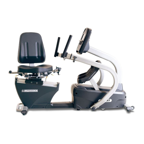
- Page 1 Owner’s Manual Model No. 16807958000 CRS800S - Assembly - Operation - Adjustments - Parts - Warranty CAUTION: You must read and understand this owner’s manual before operating unit. Retain For Future Reference...
-
Page 2: Table Of Contents
TABLE OF CONTENTS PRODUCT REGISTRATION…………………….………………………... 2 SAFETY PRECAUTIONS…………………………………..……………… 3 IMPORTANT SAFETY INSTRUCTIONS………………..………………. 4 IMPORTANT ELECTRICAL INSTRUCTIONS …………..…………….. IMPORTANT OPERATION INSTRUCTIONS …………..……………… 6 ASSEMBLY INSTRUCTIONS……………………………..……………. RECUMBENT STEPPER SETUP……………………………………….. OPERATION OF YOUR SEMI-RECUMBENT STEPPER…………….. 13 PROGRAMMABLE FEATURES…………..……………..……………. …. 17 USING A HEART RATE TRANSMITTER………………..……………… 23 EXPLODED VIEW DIAGRAM…...………………...……..………………... -
Page 3: Product Registration
CONGRATULATIONS ON YOUR SEMI-RECUMBENT STEPPER Thank you for your purchase of this quality Semi-Recumbent Stepper from Dyaco Canada Inc. Your new Semi-Recumbent Stepper was manufactured by one of the leading fitness manufacturers in the world and is backed by one of the most comprehensive warranties available. -
Page 4: Safety Precautions
SAFETY PRECAUTIONS IMPORTANT SAFETY INFORMATION THIS UNIT IS INTENDED FOR HOUSEHOLD USE ONLY READ ALL INSTRUCTIONS BEFORE USING THIS SEMI-RECUMBENT STEPPER CAUTION: Before starting any exercise program, it is recommended that you consult your physician. Thank you for purchasing our product. Even though we go to great efforts to ensure the quality of each product we produce, occasional errors and/or omissions do occur. -
Page 5: Important Safety Instructions
IMPORTANT SAFETY INSTRUCTIONS WARNING - Read all instructions before using this appliance. DANGER - To reduce the risk of electric shock disconnect your Semi-Recumbent Stepper from the electrical outlet prior to cleaning and/or service work. WARNING - To reduce the risk of burns, fire, electric shock, or injury to persons, install the Semi-Recumbent Stepper on a flat level surface with access to a 110-volt, 15-amp grounded outlet with only the Semi-Recumbent Stepper plugged into the circuit. -
Page 6: Important Electrical Instructions
IMPORTANT ELECTRICAL INSTRUCTIONS WARNING! NEVER remove any cover without first disconnecting AC power. If voltage varies by ten percent (10%) or more, the performance of your Semi-Recumbent Stepper may be affected. Such conditions are not covered under your warranty. If you suspect the voltage is low, contact your local power company or a licensed electrician for proper testing. -
Page 7: Important Operation Instructions
IMPORTANT OPERATION INSTRUCTIONS NEVER operate this Semi-Recumbent Stepper without reading and completely understanding the results of any operational change you request from the computer. Understand that changes in resistance do not occur immediately. Set your desired resistance on the computer console and release the adjustment key. The computer will obey the command gradually. -
Page 8: Assembly Instructions
ASSEMBLY INSTRUCTIONS Unpacking 1. Cut the straps, then lift the box over the unit and unpack. 2. Carefully remove all parts from the carton and inspect for any damage or missing parts. If parts are damaged or missing, contact your dealer immediately. 3. - Page 9 HARDWARE FOR STEP 1 PART TYPE DESCRIPTION Q'TY HEX HEAD BOLT 3/8" × 3-1/4" HEX HEAD BOLT 3/8" × 2" HEX HEAD BOLT 5/16" × 1-1/4" PHILLIPS HEAD SCREW M5×12 FLAT WASHER 3/8" FLAT WASHER 8.5×26×2T NYLOC NUT 3/8"×7T NYLOC NUT 5/16"×6T STEP 1: 1.
- Page 10 HARDWARE FOR STEP 2 PART TYPE DESCRIPTION Q'TY BUTTON HEAD BOLT 5/16" x 1-3/4" HEX HEAD BOLT M8 x 16 HEX HEAD BOLT 3/8" x 2-1/2" FLAT WASHER 3/8"x19x1.5T CURVED WASHER 8×23×1.5T NYLOC NUT 3/8"x7T NYLOC NUT 5/16"x 6T SPLIT WASHER 10x2T STEP 2: 1.
- Page 11 HARDWARE FOR STEP 3 PART TYPE DESCRIPTION Q'TY HEX HEAD BOLT M6x25 FLAT WASHER 3/8" x 25x 2T NYLOC NUT 3/8" x 7T HEX HEAD BOLT 3/8" x 1-3/4" STEP 3: 1. Put the SEAT CUSHION on the SEAT CARRIAGE and secure with HEX HEAD BOLTS (145). 2.
- Page 12 HARDWARE FOR STEP 4 PART TYPE DESCRIPTION Q'TY PHILLIPS HEAD SCREWS M5 x 12 BUTTON HEAD BOLT 3/8" x 3/4" FLAT WASHER 3/8" x 19 x 1.5T CURVED WASHER 10x 21.3 x 7.8T SPLIT WASHER 10x 2T STEP 4: 1. Connect the cables out of the mast to the CONSOLE (27), and use PHILLIPS HEAD SCREWS (155) to secure it.
-
Page 13: Recumbent Stepper Setup
RECUMBENT STEPPER SETUP SEAT ROTATION Lift left lever and hold while rotating the seat to desired position. Release lever. EAT RECLINE Lift right lever and hold while adjusting seat position to the desired position. Release lever. SEAT FOR/AFT ADJUSTMENT Lift lever and hold while adjusting seat position to the desired distance from the console. -
Page 14: Operation Of Your Semi-Recumbent Stepper
OPERATION OF YOUR SEMI-RECUMBENT STEPPER Integrated Speakers for MP3 Player Muscle Activation Profile Large LCD with scrolling feedback and scrolling message center Heart Rate % Profile Swivel Fan to keep you cool Ten innovative programs offer a variety of workouts Convenient cargo Easy-Touch compartment for... - Page 15 DOT MATRIX CENTER DISPLAY Twenty columns of boxes (8 high) indicate each segment of a workout. The boxes only show an approximate level (resistance) of effort. They do not necessarily indicate a specific value - only an approximate percent to compare levels of intensity. In Manual Operation the resistance dot matrix window will build a profile “picture”...
- Page 16 MUSCLE ACTIVATION FIGURE There is an anatomical figure located at the top of the console. This figure will light all areas that are activated when using the Semi-Recumbent Stepper. These will light up during any of the programs. You can control which muscles are activated by customizing the resistance profile during the set up phase of console programming.
- Page 17 BASIC INFORMATION The Message Center will initially be displaying the Program name. When in scan mode during a program, METS will be displayed for four seconds, then move on and display Segment time, Max level. Pressing the ENTER key again will bring you back to the beginning. The STOP key actually has several functions.
-
Page 18: Programmable Features
ENTERING A PROGRAM AND CHANGING SETTINGS When you enter a program, by pressing a program key, then Enter key, you have the option of entering your own personal settings. If you want to work out without entering new settings, then just press the Start key. - Page 19 PRESET PROGRAMS The Semi - Recumbent Stepper has five different programs that have been designed for a variety of workouts. These five programs have factory preset work level profiles for achieving different goals. HILL RESISTANCE LEVEL This program follows a triangle or pyramid type of gradual progression from approximately 10% of maximum effort (the level that you chose before starting this program) up to a maximum effort which lasts for 10% of the total workout time, then a gradual...
- Page 20 PROGRAMMING PRESET PROGRAMS 1. Select the desired program key then press the Enter key. 2. The Message Center will ask you to enter your Age. You may adjust the age setting, using the Level Up/Down keys, then press the Enter key to accept the new number and proceed on to the next screen.
- Page 21 CUSTOM USER DEFINED PROGRAMS There are two customizable User programs that allow you to build and save your own workout. The two programs, User 1 and User 2, operate exactly the same way so there is no reason to describe them separately.
- Page 22 HEART RATE PROGRAMS A word about Heart Rate: The old motto, “no pain, no gain”, is a myth that has been overpowered by the benefits of exercising comfortably. A great deal of this success has been promoted by the use of heart rate monitors. With the proper use of a heart rate monitor, many people find that their usual choice of exercise intensity was either too high or too low and exercise is much more enjoyable by maintaining their heart rate in the desired benefit range.
- Page 23 RATE OF PERCEIVED EXERTION Heart rate is important but listening to your body also has a lot of advantages. There are more variables involved in how hard you should workout than just heart rate. Your stress level, physical health, emotional health, temperature, humidity, the time of day, the last time you ate and what you ate, all contribute to the intensity at which you should workout.
-
Page 24: Using A Heart Rate Transmitter
USING A HEART RATE TRANSMITTER (OPTIONAL) How to wear your wireless chest strap transmitter: 1. Attach the transmitter to the elastic strap using the locking parts. 2. Adjust the strap as tightly as possible as long as the strap is not too tight to remain comfortable. - Page 25 HEART RATE PROGRAM OPERATION Note: You must wear the heart rate transmitter strap for these programs Both programs operate the same, the only difference is that HR1 is set to 60% and HR2 is set to 80% of the maximum heart rate. They both are programmed the same way. To start an HR program follow the instructions below or just select the HR1 or HR2 program, then the Enter key and follow the directions in the Message Center.
-
Page 26: Exploded View Diagram
EXPLODED VIEW DIAGRAM Customer Service 1-888-707-1880 Dyaco Canada Inc. 2019 Email: customerservice@dyaco.ca... -
Page 27: Parts List
PARTS LIST KEY NO. PART NO. DESCRIPTION Q'TY 9580001 Main Frame 9580002 Console Mast 9580003 Swing Arm (R) 9580004 Swing Arm (L) 9580005 Pedal Plate (R) 9580006 Pedal Plate (L) 9580007 Handle Slider (R) 9580008 Handle Slider (L) 9580009 Drive Pulley 9580010 Lower Linkage A 9580011... - Page 28 KEY NO. PART NO. DESCRIPTION Q'TY 9580043 Adjustable Idler Wheel Axle 9580044 Lower Linkage 9580045 Safety Cover 9580046 Rotate Disk 9580047 Scale Arrowhead 9580048 Flywheel Axle Set Collar (R) 9580049 Cable Guide Wheel Axle 9580050 Shroud Bracket 9580051 Sensor Bracket 9580052 Shroud Fixing Plate 9580053...
- Page 29 KEY NO. PART NO. DESCRIPTION Q'TY 9580088 Ø7_HGP Wire Grommet 9580089 Button Head Plug 9580090 Lever Anchor 9580091 Seat Back Cover 9580092 Square End Cap 9580093 Main Frame Housing 9580094 Quick Release 9580095 Seat Stop Axle 9580096 Axle 9580097 Ø52 × Ø40 × 28L_Bearing 9580098 Adjusting Plate (L) 9580099...
- Page 30 KEY NO. PART NO. DESCRIPTION Q'TY 95800138 M6 × 10m/m_Button Head Socket Bolt 95800139 M8 × 20m/m_Button Head Socket Bolt 95800140 M8 × 25m/m_Button Head Socket Bolt 95800141 5/16" × UNC18 × 95m/m_Button Head Socket Bolt 95800142 M5 × P0.8 × 15m/m_Socket Head Cap Bolt 95800143 M6 ×...
- Page 31 KEY NO. PART NO. DESCRIPTION Q'TY 95800183 Ø8 × 1.5T_Spring Washer 95800184 Ø5 × 1.5T_Spring Washer 95800185 M6 × 1T_Spring Washer 95800186 Ø17_C Ring 95800187 Ø10_C Ring 95800188 Ø16_C Ring 95800189 Ø40_C Ring 95800190 3/8" × 2"_Flat Head Socket Bolt 95800191 M5 ×...
-
Page 32: General Maintenance
GENERAL MAINTENANCE 1. Wipe down all areas in the sweat path with a damp cloth after each workout. 2. If a squeak, thump, clicking or rough feeling develops the main cause is most likely one of two reasons: I. The hardware was not sufficiently tightened during assembly. All bolts that were installed during assembly need to be tightened as much as possible. - Page 33 ENGINEERING MODE MENU The console has built in maintenance/diagnostic software. The software will allow you to change the console settings from English to Metric and turn off the beeping of the speaker when a key is pressed for example. To enter the Engineering Mode Menu, press and hold down the Start, Stop and Enter keys.
-
Page 34: Training Guidelines
TRAINING GUIDELINES Exercise Exercise is one of the most important factors in the overall health of an individual. Listed among its benefits are: Increased capacity for physical work (strength endurance) Increased cardiovascular (heart and arteries/veins) and respiratory efficiency ... - Page 35 Overload This is where you exercise at a level above that which can be carried out comfortably. The intensity, duration and frequency of exercise should be above the training threshold and should be gradually increased as the body adapts to the increasing demands. As your fitness level improves, so the training threshold should be raised.
- Page 36 The following table is a guide to those who are “starting fitness”. Target heart Rate 10 Second Count Beats per Minute 132 126 120 Pulse Count The pulse count (on your wrist or carotid artery in the neck, taken with two index fingers) is done for ten seconds, taken a few seconds after you stop exercising.
- Page 37 Patronization This is the term used to vary your exercise program for both physiological and psychological benefits. In your overall program, you should vary the workload, frequency and intensity. The body responds better to variety and so do you. In addition, when you feel yourself getting “stale’, bring in periods of lighter exercise to allow the body to recuperate and restore its reserves.
-
Page 38: Stretching
STRETCHING Stretching should be included in both your warm up and cool down, and should be performed after 3-5 minutes of low intensity aerobic activity or callisthenic type exercise. Movements should be performed slowly and smoothly, with no bouncing or jerking. Move into the stretch until slight tension, not pain, is felt in the muscle and hold for 20-30 seconds. - Page 39 TOUCHES INNER THIGH STRETCH Slowly bend forward from your Sit with the soles of your feet together waist, letting your back and with your knees pointing outward. Pull shoulders relax as you stretch your feet as close into your groin as toward your toes.
-
Page 40: Manufacturer's Limited Warranty
MANUFACTURER’S LIMITED WARRANTY Dyaco Canada Inc. warrants all its bike parts for a period of time listed below, from the date of retail sale, as determined by a sales receipt. Dyaco Canada Inc.’s responsibilities include providing new or remanufactured parts, at Dyaco Canada Inc.’s option, and technical support to our independent dealers and servicing organizations. - Page 41 Please visit us online for information about our other brands and products manufactured and distributed by Dyaco Canada Inc. www.dyaco.ca www.dyaco.ca www.dyaco.ca www.dyaco.ca www.spiritfitness.ca www.spiritfitness.ca www.dyaco.ca www.dyaco.ca www.trainorsports.ca www.solefitness.ca www.dyaco.ca www.dyaco.ca www.xterrafitness.ca www.dyaco.ca Customer Service 1-888-707-1880 Dyaco Canada Inc. 2019 Email: customerservice@dyaco.ca...
Need help?
Do you have a question about the CRS800S and is the answer not in the manual?
Questions and answers
Re: Spirit CRS 800S Recumbent stepper. Getting an error message and not able to set the desired level of difficulty. Unplugged it for ten minutes and plugged it back but nothing changed. I live in Pennsylvania and the bike is in Florida. I purchased it for my elderly and infirmed mom.
If a Spirit CRS800S Recumbent Stepper displays an error message and does not allow setting the desired level of difficulty, do not attempt any customizing, adjustments, repair, or maintenance not described in the manual. Contact the dealer or Spirit Fitness customer service for assistance.
This answer is automatically generated