Table of Contents
Advertisement
Quick Links
Advertisement
Table of Contents

Related Manuals for AnyDATA EMII-800


Summary of Contents for AnyDATA EMII-800
- Page 1 Interface Description EMII-800 Service Manual Application Information SERVICE MANUAL 800M CDMA Wireless Kit EMII-800 AnyDATA.NET Inc. Hanvit Bank B/D 6F Byulyang-dong Kwachon KOREA Tel) 82-2-504-3360 Fax) 82-2-504-3362 EMII-800 V1.0 AnyDATA.NET Proprietary Use Subject to Restrictions...
- Page 2 AnyDATA.NET Inc. assumes no responsibility for any loss or claims by third parties, which may arise through the use of its products. AnyDATA.NET Inc. assumes no responsibility for any damage or loss caused by the deletion or loss of data as a result of malfunctions or repairs.
- Page 3 Interface Description EMII-800 Service Manual Application Information CAUTION Operating Requirements The user can not make any changes or modifications not expressly approved by the party responsible for compliance, otherwise it could void the user's authority to operate the equipment. To satisfy FCC RF exposure compliance requirements for a mobile transmitting device, this device and its antenna should generally maintain a separation distance of 20cm or more from a person…s body.
-
Page 4: Table Of Contents
Interface Description EMII-800 Service Manual Application Information Table of Contents General Introduction ........................... 2 CHAPTER 1. System Introduction 1. System Introduction ....................3 2. Features and Advantages of CDMA Module ............4 3. Structure and Functions of CDMA Module ............ - Page 5 Interface Description EMII-800 Service Manual Application Information General Introduction EMII-800 functions digital cellular module worked in CDMA (Code Division Multiple Access) mode. CDMA type digital mode applies DSSS (Direct Sequence Spread Spectrum) mode which is used in military. This feature enables the phone to keep communication from being crossed and use one frequency channel by multiple users in the same specific area, resulting that it increases the capacity 10 times more compared with that in the analog mode currently used.
-
Page 6: Chapter 1. System Introduction
EMII-800 CHAPTER 1. System Introduction 1. System Introduction 1.1 CDMA Abstract The cellular system has a channel hand-off function that is used for collecting the information on the locations and movements of radio mobile telephones from the cell site by automatically controlling several cell site through the setup of data transmission routes and thus, enabling one switching system to carry out the automatic remote adjustment. -
Page 7: Features And Advantages Of Cdma Module
Interface Description EMII-800 Service Manual Application Information 2. Features and Advantages of CDMA Module 2.1 Various Types of Diversities In the CDMA broadband modulation(1.25MHz band), three types of diversities (time, frequency, and space) are used to reduce serious fading problems generated from radio channels in order to obtain high-quality calls. - Page 8 Interface Description EMII-800 Service Manual Application Information 2.3 Voice Encoder and Variable Data Speed The bi-directional voice service having variable data speed provides voice communication which employs voice encoder algorithm having power variable data rate between the mobile telephone cell site and mobile station. On the other hand, the transmit voice encoder performs voice sampling and then, creates encoded voice packets to be sent out to the receive voice encoder, whereas the receive voice encoder demodulates the received voice packets into voice samples.
- Page 9 Interface Description EMII-800 Service Manual Application Information and accordingly, interference is reduced by 1/3 on the average and the capacity that can be supported by the entire system is increased by three times. 2.7 Soft Capacity The subscriber capacity of CDMA system is flexible depending on the relation between the number of users and service classes.
-
Page 10: Structure And Functions Of Cdma Module
Interface Description EMII-800 Service Manual Application Information 3. Structure and Functions of CDMA Module The mobile station of CDMA system is made up of a radio frequency part and logic/control (digital) part. The mobile station is fully compatible with the existing analog FM system. The mobile station antenna is connected with the transmitter/receiver via a duplexer filter so that it can carry out the transmit/receive function at the same time. -
Page 11: Specification
Interface Description EMII-800 Service Manual Application Information 4. Specification 4.1 General Specification 4.1.1 Transmit/Receive Frequency Interval : 45 MHz 4.1.2 Number of Channels (Channel Bandwidth) CDMA : 20 CH (BW: 1.23MHz) 41.3 Operating Voltage : DC 6~12V 4.1.4 Operating Temperature : -30 ° ~ +60 °... - Page 12 Interface Description EMII-800 Service Manual Application Information 4.3 Transmit Specification 4.3.1 Frequency Range 824.04 MHz ~ 848.97 MHz 4.3.2 Local Oscillating Frequency Range : 966.88 MHz 12.5 MHz 4.3.3 Intermediate Frequency : 130.38 MHz 4.3.4 Output Power: 0.32W 4.3.5 Interference Rejection 1) Single Tone : -101dBm with Jammer of -30dBm at 900 kHz 2) Two Tone : -101dBm with Jammer of -43dBm at 900 kHz &...
- Page 13 Interface Description EMII-800 Service Manual Application Information 4.4 MS (Mobile Station) Transmitter Frequency FA NO. CH.NO. CENTER FREQUENCY FA NO. CH.NO. CENTER FREQUENCY 1011 824.640 MHz 837.120 MHz 825.870 MHz 838.350 MHz 827.100 MHz 839.580 MHz 828.330 MHz 840.810 MHz 829.560 MHz...
-
Page 14: Chapter 2. Nam Input Method(Inputting Of Telephone Numbers Included)
Interface Description EMII-800 Service Manual Application Information CHAPTER 2. NAM Input Method 1.INSTALLATION METHOD HeadSet Power Supply (6~12V) 8 Pin to 9 Pin Cable COM1 1) Supply the voltage of 6~12V 2pin Connector of the EMII-800. 2) Connect the UART1 to PC COM1 port with the RS-232C cable. - Page 15 Interface Description EMII-800 Service Manual Application Information 2. OPERATION METHOD 1) Run PSTDM program at Windows95 or Windows98 2) Set Buad rate to the modem…s. 3) Click [DM mode] EMII-800 V1.0 AnyDATA.NET Proprietary Use Subject to Restrictions...
- Page 16 Interface Description EMII-800 Service Manual Application Information 4) If OK is displayed in the message box, modem is now ready for communication with PC. 5) Click MENU BAR icon. EMII-800 V1.0 AnyDATA.NET Proprietary Use Subject to Restrictions...
- Page 17 Interface Description EMII-800 Service Manual Application Information SCRIPTINPUT WINDOW 6) As shown in the picture above, service file input plane will be displayed (See if clock is running. If it isn…t, communication with PC is not activated. Repeat step 1 through 5, or reset the power of modem and repeat step 1 through 5 ) 7) Type NAM Programming script like the example shown below, <NAM Programming script example>...
-
Page 18: Chapter 3. Circuit Description
Interface Description EMII-800 Service Manual Application Information CHAPTER 3. Circuit Description 1. Overview IFR3000 receives modulated digital signals from the MSM of the digital circuit and then, changes them into analog signals by the digital/analog converter (DAC, D/A Converter) in order to create baseband signals. Created baseband signals are changed into IF signals by RFT3100 and then, fed into the Mixer after going through AGC. - Page 19 Interface Description EMII-800 Service Manual Application Information and driver amplifier providing overall board area and cost savings. RFT3100 functionality is specifically controlled from the MSM5100 via the three-line serial bus interface (SBI). Designed to meet the requirements for global CDMA markets, the RFT3100 will operate over the...
- Page 20 Interface Description EMII-800 Service Manual Application Information antenna in order to prevent any damages on circuits, that may be generated by output signals reflected from the duplexer and re-inputted to the power amplifier output end. 2.6. Description of Frequency Synthesizer Circuit 2.6.1 Voltage Control Temperature Compensation Crystal Oscillator(TCX201, VCTCXO)
-
Page 21: Digital/Voice Processing Part
Interface Description EMII-800 Service Manual Application Information 3. Digital/Voice Processing Part 3.1 Overview The digital/voice processing part processes the user's commands and processes all the digital and voice signal processing in order to operate in the phone. The digital/voice processing part is made up of a receptacle part, voice processing part, mobile station modem part, memory part, and power supply part. - Page 22 Interface Description EMII-800 Service Manual Application Information 3.3 Circuit Description Receptacle Ringer MSM5100 (16M+4M) Earpiece AUDIO Processor Power Supply [Figure 3-1] Block Diagram of Digital/Voice Processing Part 3.3.1 MSM Part MSM5100, which is U401, is the core element of CDMA system terminal that includes ARM7TDMI microprocessor core.
- Page 23 Interface Description EMII-800 Service Manual Application Information 3.3.2 Memory Part Memory part, MCP consists of 16M Flash memory and 4M static RAM. In the MCP, there are programs used for terminal operation. The programs can be changed through down loading after the assembling of terminals and data generated during the terminal operation are stored temporarily and non-volatile data such as unique numbers (ESN) of terminals are stored.
-
Page 24: Level Translator Part
Interface Description EMII-800 Service Manual Application Information 4. Level Translator Part 4.1 EMII-800 supply power to Modem(4.0V). [Fig 4-1] The Block Diagram of Source (in brief) 4.2 UART Interface The Universal Asynchronous Receiver Transmitter (UART) communicates with serial data that conforms the RS-232 Interface protocol. - Page 25 Interface Description EMII-800 Service Manual Application Information 4.2.2 Signal level of RXD/TXD DTSS -800 EMII-800 SIPEX207 MSM_input Vout= 2.8V RS232 MSM_output RS232 PHONE TX01 RX02 TX04 RX03 = 7.68V = 6.50V = 3.00V = 3.9V = -7.68V = -6.64V = 0V...
-
Page 26: Chapter 4. Fcc Notice
Interface Description EMII-800 Service Manual Application Information CHAPTER 4. FCC Notice This equipment has been tested and found to comply with the limits for a Class B digital device, pursuant to part 15 of the FCC Rules. These limits are designed to provide reasonable protection against harmful interference in a residential installation. - Page 27 Interface Description EMII-800 Service Manual Application Information APPENDIX 1. Assembly and Disassembly Diagram 2. Block & Circuit Diagram 3. Part List 4. Component Layout EMII-800 V1.0 AnyDATA.NET Proprietary Use Subject to Restrictions...
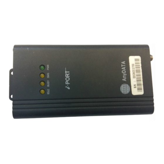
- Page 28 Interface Description EMII-800 Service Manual Application Information 1. Assembly and Disassembly Diagram DC6~12V RS232C INPUT IDLE BUSY SMS i PORT AnyDATA EAR-MIC DEBUG CDMA ANT EMII-800 V1.0 AnyDATA.NET Proprietary Use Subject to Restrictions...
- Page 29 Interface Description EMII-800 Service Manual Application Information 2. Block & Circuit Diagram 2.1. MODEM Block Diagram 2.2. EMII-800 Block Diagram EMII-800 V1.0 AnyDATA.NET Proprietary Use Subject to Restrictions...
- Page 30 Interface Description EMII-800 Service Manual Application Information UART1 RS-232 RF Unit MSM Inter. EARJACK CODEC MSM5100 External PWR LDO(4V) (6~14V) DTSS-800 Application Device EMII-800 3. Part List 3-1. MODEM Part List V0.4 2002.01.07 COMPONENT NAME DESCRIPTION Lay. DESIGN NUMBER Q'ty...
- Page 31 Interface Description EMII-800 Service Manual Application Information 16 NT732ATD683K THERMISTOR TOP TH201 17 F0805B3R00FW FUSE (2012 Size) TOP FUSE1 RM912 TOP U103 CONEXANT FAR-D5CC DUPLEXER TOP DUP101 FUJITSU BFP420 BUFFER AMP BOT U203 EPCOS B4943 RX IF SAW FILTER TOP FL103...
- Page 32 Interface Description EMII-800 Service Manual Application Information GRM36C0G010C50PT 1pF-1005 Cap TOP C168 MURATA GRM36C0G1R5C50PT 1.5pF-1005 Cap TOP C104 MURATA GRM36COG020C50PT 2pF-1005 Cap BOT C249 MURATA GRM36C0G030C50PT 3pF-1005 Cap TOP C113 MURATA TOP C186 MURATA GRM36COG040D50PT 4pF-1005 Cap BOT C135 MURATA...
- Page 33 Interface Description EMII-800 Service Manual Application Information C289,C284,C219,C470,C144, MURATA C136,C137 C258,C209,C118,C128,C620, C630,C455,C622,C611,C603, MURATA C641,C618,C453 18 GRM36COG103J50PT 10nF-1005 Cap C283,C290,C215,C250,C216, C205,C206,C220,C221,C614, MURATA C110,C450,C460,C410,C701, C130 19 GRM36COG123J50PT 12nF-1005 Cap BOT C425,C427 MURATA TOP C421 20 GRM36Y5V223Z25PT 22nF-1005 Cap MURATA BOT C420 21 GRM36COG333J50PT...
- Page 34 Interface Description EMII-800 Service Manual Application Information 36 TA-6R3TCMS4R7M-PR Tan Cap (4.7uF/6.3V/P) TOP C124 TOWA 37 TA-6R3TCR330K-A Tan Cap (33uF/6.3V/A) TOP C606,C419 TOWA 38 514756A , SPRAGUE Tan Cap(100uF/6.3V/595D-B) TOP C626,C125 SPRAGUE RESISTOR R156,R221,R123,R133,R426, ROHM MCR01MZSJX000 0W 5%-1005 Resistor R134,R136...
- Page 35 Interface Description EMII-800 Service Manual Application Information 21 MCR01MZSJX822 8.2KW 5%-1005 Resistor BOT R209 ROHM R204,R205,R126,R128,R316, R307,R305,R701,R311,R314, ROHM 22 MCR01MZSJX103 10KW 5%-1005 Resistor R312,R475 R235,R208,R207,R424,R425, ROHM R502,R501,R114,R116,R102 23 MCR01MZSJX223 22KW 5%-1005 Resistor TOP R313,R315,R310,R330 ROHM 24 MCR01MZSJX363 36KW 5%-1005 Resistor...
- Page 36 Interface Description EMII-800 Service Manual Application Information 3-2. EM Main Board Partlist 28. Jan. 2002 Commponent Name Description DESIGN NO Vendor LOGIC 1 SMA R/A(F)+ MCA Cable SMA(F) + MCA CDMA LINK Tec. 2 PH127-60SMD-16H-2.0 60pin connetor SKY Elec. 3 TC7SHU04F...
- Page 37 Interface Description EMII-800 Service Manual Application Information 25 EM(II)_PCB _V0.1 EM(II)_PCB_MAIN_ V0.1 UNIC Elec. 26 EM-BODY-00 BODY TOSUNG 27 EM-FRONT-00 FRONT TOSUNG 28 EM-REAR-00 REAR TOSUNG R4,R13,R14,R15, R16, R17,R18,R19, 29 DNI RESISTOR R20,R21,R22,R23, R24,R25,R26,R27, R40,R41,R42,R43 30 DNI CAPACITOR C3,C4 31 DNI...
- Page 38 Interface Description EMII-800 Service Manual Application Information 4. Component Layout EMII-800 V1.0 AnyDATA.NET Proprietary Use Subject to Restrictions...
Need help?
Do you have a question about the EMII-800 and is the answer not in the manual?
Questions and answers