Dyson DC18 Service Manual
Hide thumbs
Also See for DC18:
- Owner's manual (16 pages) ,
- Operating manual (16 pages) ,
- Manual (16 pages)
Advertisement
Quick Links
Advertisement

Related Manuals for Dyson DC18


Summary of Contents for Dyson DC18
- Page 1 service manual Issued 10/06...
- Page 2 The lightweight that doesn’t lose suction. Telescope Reach wand DC18 key technology; Quick-draw wand for instant high reach cleaning. No running costs Lifetime filters that never need replacing - just wash every three Clear bin to six months.
-
Page 3: Product Overview
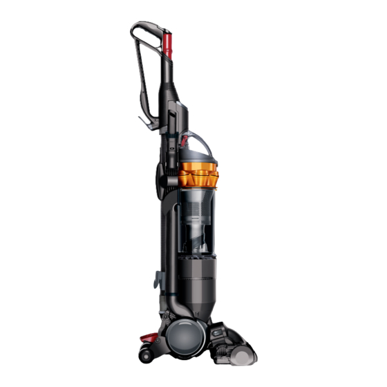
Product overview Introduction Variants DC18 overview Specifications Technical information Electrical testing Electrical resistance values Electrical circuit Electrical fault diagnostic Fitting notes General notes Motor replacement - removal Motor replacement - fitting Yoke assembly - removal Yoke assembly - fitting... - Page 4 Introduction This manual is written specifically for Dyson trained engineers and covers the DC18 range. The service instructions assume the engineer has the approved tools and test equipment with them. Variants all floors allergy DC18 overview At only 6.6kg Dyson Slim is the new lightweight that doesn’t lose suction. Like DC15, conventional wheels have been replaced with a single ball.
-
Page 5: Specifications
Testing DC18 for correct insulation The following insulation tests MUST be carried out prior to and on completion of all services to DC18, and BEFORE any functional checks. You must ensure that a full visual inspection of the product is completed prior to any service activity. - Page 6 service manual Test results An insulation test reading of between 2 MΩ and infinity is acceptable. A reading of below 2 MΩ is not considered safe and further investigation, rectification and testing must be completed before the product is used. Electrical resistance values TEST BETWEEN POINTS OHMS...
- Page 7 service manual Electrical circuit Brushbar Main On/Off Switch Switch LIVE NEUTRAL Switch area Vac motor Upright area Micro Switch Vac Motor BB Motor Rectifier Board Cleaner head assembly 15 16 Reset Switch Issued 10/06...
- Page 8 The brushbar motor can be switched off using the brushbar switch. 2) The vacuum motor of DC18 is fitted with a heat sensitive Thermal Cut-Out (TCO). This will shut the motor down for up to 60 minutes if it reaches a temperature >96 degrees celcius. Excessive temperatures within the motor are usually caused by machine/filter blockages.
- Page 9 All screws used in DC18 are M3.5 x 16 Torx T-15 unless otherwise stated. All female terminal clips used in DC18 contain a locking mechanism. The release pip will need to be activated before separation from the male terminal can occur.
- Page 10 service manual Undo and remove the two cheesehead screws in the lower cable winder. Twist the post filter cover to remove the post filter cover and post filter from the motor retainer ring. Pull the lower cable winder off the rear of the duct assembly.
- Page 11 service manual Undo the four screws in the motor retainer Undo the three screws in the motor retainer. ring. Pull the motor retainer ring and post motor Lift the motor retainer off the motor. seal out of the duct assembly. Pull the motor retaining seal out of the duct Lift the motor out of the inner bucket.
- Page 12 service manual Motor replacement - fitting Press the motor inlet seal onto the base of the motor ensuring that all edges of the seal are in full contact with the motor. Unclip both wires from the motor. Align the three locators on the motor mount with the relevant holes in the top of the motor.
- Page 13 service manual Ensure the wire is free from this screw boss Lower the motor into the inner bucket. Ensure the motor is orientated as shown (the Align the motor retainer ring over the four motor mount should align with the line on the screw bosses.
- Page 14 service manual Yoke assembly - removal Align the arrow on the HEPA filter assembly/standard post filter cage with the arrow on the post filter cover. Press the two release catches and remove the cleanerhead assembly from the front of the product.
- Page 15 service manual Firmly pull the internal hose off the Firmly pull the outer wheel hubs off either undercarriage assembly. side of the yoke assembly. Undo one of the e-clips from the end of the Remove the yoke assembly and internal hose barrel wheel axle.
- Page 16 service manual Yoke assembly - fitting Refit the e-clip onto the end of the barrel Feed the coiled cable assembly through the wheel axle. opening in the front of the yoke assembly. Position the coiled cable assembly grommet Position the yoke assembly onto the front of onto the locator on the swivel.
- Page 17 service manual Undercarriage assembly - removal B B e e f f o o r r e e c c o o n n t t i i n n u u i i n n g g t t h h e e f f o o l l l l o o w w i i n n g g p p a a r r t t s s s s h h o o u u l l d d b b e e r r e e m m o o v v e e d d a a s s p p r r e e v v i i o o u u s s l l y y s s h h o o w w n n : : Yoke assembly (pages 11 to 12).
- Page 18 service manual Undo the four cheesehead screws in the front of the undercarriage assembly. Remove the micro switch cover from the side of the undercarriage assembly. Carefully release the micro switch from the Remove the undercarriage assembly from housing. the base of the duct assembly. Whilst doing so ensure the micro switch assembly and coiled cable assembly are fed carefully through the undercarriage assembly.
- Page 19 service manual Undercarriage assembly - fitting Carefully locate the upright micro switch onto Ensure the duct seal is located onto the the two retaining pips in the undercarriage base of the duct assembly. assembly. Dress the wires neatly into the channel. Refit the micro switch cover and T-8 screw.
- Page 20 service manual Switch cover and powercord assembly - removal Unclip the connection insulator. Detach the neutral wires. Undo the four screws in the rear of the duct assembly. Release the switch cover from the two catches on the front of the duct assembly using Firmly remove the powercord from the duct a thin flat bladed screwdriver.
- Page 21 service manual Switch cover and powercord assembly - fitting Fit one of the switches into the housing. Fit the cable protector onto the powercord. Attach the live wire from the powercord to the Firmly press the powercord into the duct assembly. switch.
- Page 22 -10pm 7 days a www.dyson.c Press both switches into the ON position. Lower the switch cover onto the duct assembly with both buttons protruding from the top. Clip Assemble the brushbar reset arm and the base of the switch cover only onto the duct.
- Page 23 service manual Duct replacement - dismantle B B e e f f o o r r e e c c o o n n t t i i n n u u i i n n g g t t h h e e f f o o l l l l o o w w i i n n g g p p a a r r t t s s s s h h o o u u l l d d b b e e r r e e m m o o v v e e d d a a s s p p r r e e v v i i o o u u s s l l y y s s h h o o w w n n : : Motor assembly (pages 6 - 9) Yoke assembly (pages 11 to 12)
- Page 24 service manual Duct replacement - assemble Lower the inner bucket into the new duct assembly. Note: ensure the grommets on the Locate the lower duct cover seal into the coiled cable and micro swich loom seal against base of the duct. the openings in the base of the duct.
- Page 25 service manual Sub assemblies - cleaner head - dismantle Locate the cyclone release catch spring between the cyclone release catch and duct Undo the endcap fasteners from either side assembly. of the brush housing using a large flat bladed screwdriver or coin. Refit the exhaust seal onto the duct assembly.
- Page 26 service manual If necessary the soleplate rollers and axles Remove the two screws in the lower brushbar can be removed using a thin flat bladed motor cover. screwdriver. Remove the five Philips screws in the Remove the lower brushbar motor cover soleplate assembly.
- Page 27 service manual Carefully disconnect the wires on the TCO Lift the brushbar motor out of the brush reset switch. housing. Lift the TCO reset switch out of the Disconnect the wires from the motor tags. brushbar motor cover. If replacing the motor it will be necessary to remove the O’ring from the old brushbar motor Carefully slide the PCB assembly out of the and fit onto the new.
- Page 28 service manual Push the bumper off the front of the brush housing. Carefully unclip and remove the cleaner head connector block wire from the PCB assembly. Remove the motor mounts if necessary from Release the cleaner head connector block the brushbar motor cover. from the brushbar motor cover using a blunt ended screwdriver.
- Page 29 service manual If replacing the brush housing, it will be necessary to remove the ropeseal and fit into the new brush housing. Lift the gimble cover off the brush housing. Remove the two cheesehead screws from the front of the brushbar motor cover. Slide the brushbar motor cover off the brush housing.
- Page 30 service manual Sub assemblies - cleaner head - assemble Refit the motor mounts onto the ribs inside Align the swivel catch spring with the locator the brushbar motor cover. on the brushbar motor cover. Press the swivel catch into place. Locate the rear of the cleanerhead Slide the brushbar motor cover onto the connector block onto the shelf in the brushbar...
- Page 31 service manual Slide the PCB assembly into the ribs in the brushbar motor cover. Slide the front motor mount into the front of the brush housing. Dress the PCB wire and cleaner head connector block wire neatly/securely into the retaining clips provided. Attach the red wire to the motor terminal.
- Page 32 service manual Position the brushbar motor onto the motor Lower the bumper onto the front of the mounts. Attach the white wire from the PCB brush housing until the two catches clip over the assembly onto the brushbar motor. retainers. Lower the soleplate onto the brush housing.
- Page 33 service manual Sub-assemblies - duct assembly Each duct motor mount can be easily removed and replaced if necessary from the duct assembly. Push the endcap assemblies onto the ends of each brushbar and twist into place. The tool clip can be prised out of the side of the duct using a screwdriver.
- Page 34 service manual Sub-assemblies - internal cable looms assembly The micro switch loom assembly, cleaner The crevice tool clip can be pushed out of head coiled cable loom assembly or internal the side of the duct with a screwdriver and a new cable assembly can be replaced.
- Page 35 service manual Sub-assemblies - undercarriage Sub-assemblies - wand assembly assembly The only part available separatly from the Undo the screw under the micro switch cover. wand handle assembly is the wand cap. To remove simply push off the top of the wand handle assembly.
- Page 36 service manual Firmly pull the wheel, washer and axle out of the undercarriage. After refitting a micro switch cam assembly, it Refit in reverse. is advisable to check for actuation. If the gimble lock pin assembly needs Slide the micro switch housing into the replacing, undo the screw in the front of the undercarriage.
- Page 37 service manual Prise the pedal lugs out the side of the undercarriage. Remove the pedal. To refit, locate the gimblelock pin into the hole in the front of the undercarriage. To fit a new pedal, press the pedal plunger down. Slide the pedal over the top of the pedal Refit the spring onto the cruciform on the plunger and into the holes in the side of the gimble lock cover.
- Page 38 service manual Prise the pedal plunger and spring out of the undercarriage assembly. After replacing the pedal or pedal plunger test the undercarriage assembly for actuation. To refit, locate the spring onto the pedal To remove the lock arm, remove the screws plunger.
- Page 39 service manual Sub-assemblies - cyclone assembly Remove the lock arm from the undercarriage assembly. To replace the cyclone cap assembly firmly Refit in reverse. twist it off the rear of the cyclone assembly. Refit in reverse. To replace the bleed valve undo the two screws in the underside of the cyclone cap assembly.
-
Page 40: Sub-Assemblies - Bin Assembly
service manual Sub-assemblies - bin assembly Should it need replacing, the bin seal To replace the bin base assembly, activate the simply pulls off the cyclone assembly. When bin base release. Then pull the bin base away refitting, ensure the locating tab on the seal from the bin until it ‘bumps’... - Page 41 service manual Electrical wiring recap Switch housing Ensure the connection insulator is securely clipped Ensure that all wires are securely clipped to the around the neutral terminals and fitted correctly switches. All wires must be securely located into into the channel provided. The neutral wires must the retaining clips provided.
- Page 42 service manual Cleaner head assembly S S c c r r e e w w b b o o s s s s S S c c r r e e w w b b o o s s s s Ensure that the wires from the PCB assembly and cleaner head connector block are securely located into all retaining clips provided and are clear of any screw bosses.
- Page 43 service manual Motor, post filter and internal cable assembly Post Filter Cover Internal Cable Looms Assy Post Filter Cage Assy HEPA Post Filter Assy Internal Cable Assy Standard Post Filter Assy Post Motor Seal Screw Motor Retainer Ring Motor Retainer Seal Screw Motor Retainer Motor Mount...
- Page 44 service manual Duct assembly, switch housing and powercord Cyclone Release Catch On/Off Button Spring Brushbar Reset Arm Spring Spring Brushbar Actuator Wand Release Catch Spring Screw Switch Connection Insulator Switch Cover Cable Protector Tool Clip Powercord Exhaust Seal Crevice Tool Clip Inlet Seal Cable Clip Screw...
- Page 45 service manual Undercarriage and yoke assembly Gimble Lock Pin Assy Duct Seal Axle Under Carriage Assy Yoke Assy Pedal Plunger Outer Wheel Hub Spring Internal Hose Assy Lock Arm Assy Pedal Stabiliser Wheel Micro Switch Cam Assy Micro Switch Cover Swivel Cover Screw Plastic Washer...
- Page 46 service manual Cyclone and bin assembly Issued 10/06...
- Page 47 service manual Cleaner head assembly End Cap Assy Left PCB Assy Cleaner Head Assy Screw Cleaner Head Connector Block Assy Brushbar Motor Cover Assy Upper Swivel Catch Gimble Cover Brush Housing End Cap Assy Right Brushbar Motor Mount Brushbar Motor Assy O-Ring Brushbar Assy...
- Page 48 service manual Wand and hose assembly Wand Cap Wand Handle Assy Hose Assy Instruction Pack Combination Tool Stair Tool Issued 10/06...
Need help?
Do you have a question about the DC18 and is the answer not in the manual?
Questions and answers