Table of Contents
Advertisement
Quick Links
Digi-Touch Digital Network
Featuring
3 Steps to installing the system
Wiring diagrams for the 3 steps
Table of binary dip switch settings 1-60
LPPK software setup
1025 Cobb Place Blvd Suite 100 Kennesaw, GA 30144 • 800-241-9173 • www.triateklighting.com
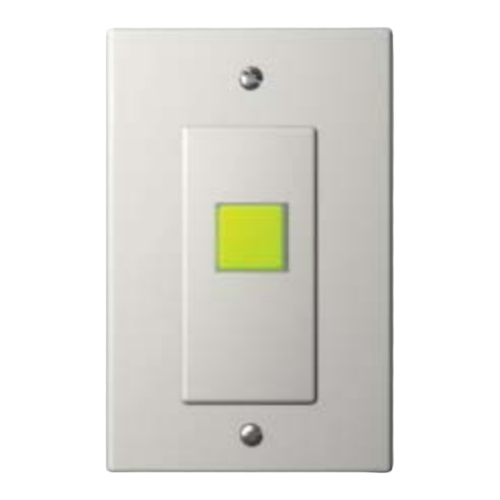
DDN-SW1 - 1 Button Switch
DDN-SW - 2 Button Switch
DDN-L - Control Board
Advertisement
Table of Contents

Related Manuals for TRIATEK DDN-SW1


Summary of Contents for TRIATEK DDN-SW1
- Page 1 Digi-Touch Digital Network DDN-SW1 - 1 Button Switch DDN-SW - 2 Button Switch DDN-L - Control Board Featuring 3 Steps to installing the system Wiring diagrams for the 3 steps Table of binary dip switch settings 1-60 LPPK software setup...
- Page 2 CAUTION: Used without the safety alert symbol, indicates a potentially hazardous situation which, if not avoided, can result in personal or property damage. Failure to comply with proper handling of the TRIATEK Lighting products may void your warranty In addition, this symbol may appear in the margin of specific portions of text as a safety reminder.
-
Page 3: Table Of Contents
Appendix A: Dip Switch Setting Tables ........... 10 Appendix B: LPPK Setup for TRIATEK Lighting Digi-Touch Systems ......11... -
Page 4: Overview
Make all connections before applying power. The DDN-Link can be used to loop power up to 8 DDN-SW switches. Two-button switches or 16 DDN-SW1 one-button switches. Make sure the Link module is wired to the panel for power and power up all auxillary power supplies. -
Page 5: Installation Steps
DDN-SW Step 1. Physical Dimensions & Dip Switch Settings a. Ensure proper size gang box and Decora plate for DDN-SW1 or DDN-SW. b. If exact settings per each location have not been pre-set, set the correct dip switch ad- dress on each module (see look-up table, Appendix A). It is helpful to use a worksheet to layout all the switch numbers for each panel before setting addresses on the switches. -
Page 6: Physical Dimensions & Dip Switch Settings For Ddn-Sw1
1.75 '' 1.5 '' 1.5 '' d. See example below for DDN-SW1 (1-button). Dip switch is “5” in binary. Thus the single button controls panel group 5. The “group” refers to group assignments made in the Triatek Lighting panel via Lighting Panel Programmer’s Kit (LPPK). -
Page 7: Step 2. Network The Digi-Touch (Ddn) Switches For Communications And Power
J3. (See Front View, previous page) d. The DDN-Link may be used to Looppower 8 DDN-SW or 16 DDN-SW1 modules up to runs of 1000 ft. See step 3. e. Additional DC power supplies may be needed for longer runs or larger numbers of switch modules. -
Page 8: Step 3. Connect The Digi-Touch Network To The Lighting Panel Cpu
Digi-Touch™ Install Guide 2 Pair 18 AWG Power 22 AWG Twisted and shielded for signal Step 3. Connect the Digital Switch Network to the DDN-Link and the Link to the Lighting panel CPU a. If the Link occurs at the end of the network (it may be in the middle), short jumper J-1 for termination resistor on Link. -
Page 9: Adding An External Power Supply
Digi-Touch™ Install Guide Adding An External Power Supply Connecting more than 8 DDN-SW or 16 DDN-SW1 Switches 3/22/2005 Page 9 of 11 1025 Cobb Place Blvd. Suite 100, Kennesaw, GA 30144 • 770-429-3043 • www.triateklighting.com... -
Page 10: Appendix A: Dip Switch Setting Tables
Dip Switch setting assigns group address to upper button, closest to the dip switch. Lower button, not present in the DDN-SW1, is automatically “address + 1”. Modules are typically addressed in order as follows: DDN-SW - 1, 3, 5, 7, 9, ... - Page 11 Appendix B: LPPK Setup for TRIATEK Lighting Digi-Touch Switches Purpose: Assign DDN-SW1 or DDN-SW switches to LPPK Groups in order to control the correct lighting circuits and report the Group status back to the correct DDN-SW1 or SW2 button LEDs.
Need help?
Do you have a question about the DDN-SW1 and is the answer not in the manual?
Questions and answers