Table of Contents
Advertisement
Quick Links
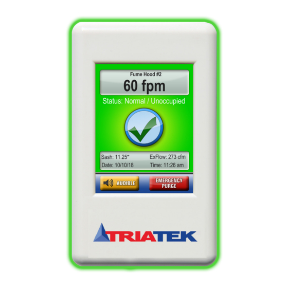
VMS-1655M
Vortex Monitoring System
Installation Guide
Overview
Use the VMS-1655M Vortex Monitor in the Flowsafe Stable Vortex II fume hood and Flowsafe Stable Vortex conversion kit to measure
and control the vortex pressure and adjust to maintain correct fume hood containment. The VMS-1655M adjusts for environmental
and usage conditions such as sash movement, fume hood loading, room pressure fluctuations, and cross drafts with active vortex
stabilization in real-time. The alarm function notifies you if there is a compromise in fume hood performance. Some of the features and
benefits include:
•
Full-color touchscreen display with programmable display options and adjustable back-light
•
360° Safety Halo
™
•
Intuitive user interface that simplifies setup and configuration of unit
•
Optional display mode to show real-time face velocity at main screen
•
Graphical hood status display
•
Audible and visual alarms
•
Multi-level password protection
•
1 analog input: 0 VDC to 10 VDC
•
2 analog outputs, actuator control, exhaust air flow feedback
•
BACnet® MS/TP network comms
•
Real-time view facility facilitates diagnostics during setup and commissioning
IMPORTANT: Make all wiring connections in accordance with the National Electrical Code and local regulations. Use proper
Electrostatic Discharge (ESD) precautions during installation and servicing to avoid damaging the electronic circuits of the VMS-
1655M Fume Hood Monitor.
IMPORTANT : Assurez-vous que tous les branchements de câbles sont effectués selon le Code national de l'électricité et les
réglementations locales. Utilisez une bonne protection contre les décharges électrostatiques (ESD) pendant l'installation et l'entretien
pour éviter d'endommager les circuits électroniques du VMS-1655M Fume Hood Monitor.
1
LIT-12013297
May 2022
Advertisement
Table of Contents

Related Manuals for TRIATEK VMS-1655M


Summary of Contents for TRIATEK VMS-1655M
-
Page 1: Overview
Overview Use the VMS-1655M Vortex Monitor in the Flowsafe Stable Vortex II fume hood and Flowsafe Stable Vortex conversion kit to measure and control the vortex pressure and adjust to maintain correct fume hood containment. The VMS-1655M adjusts for environmental and usage conditions such as sash movement, fume hood loading, room pressure fluctuations, and cross drafts with active vortex stabilization in real-time. -
Page 2: Vms-1655M Vortex Monitor
Alarm Audible button at the bottom of the touchscreen display. The VMS-1655M provides an optional Analog Input that you can use to monitor the exhaust air flow of the fume hood that uses a third party flow pressure sensor with a 0 VDC to 10 VDC output. -
Page 3: Table Of Contents
VMS-1655M Contents Overview...................................1 VMS-1655M Vortex Monitor ............................2 Isolated power supply .............................4 Installation ................................5 Installation ................................5 Mounting/wiring ...............................5 Sensor placement..............................6 Vortex sensor mounting location ...........................7 Mounting location ..............................8 Applying power ..............................9 Main display screen ............................9 Configuring vortex monitor ..........................9 Calibrating vortex sensor ............................9 Configuring face velocity alarm setpoints ......................9... -
Page 4: Isolated Power Supply
Remarque : L’actionneur est vendu séparément. Isolated power supply Figure 2: Stepdown isolation transformer, provided with the VMS-1655M Red / 24 VAC / 30VA connected to the VMS... -
Page 5: Installation
Installation The VMS-1655M incorporates two analog output signals, one is a 0 VDC to 10 VDC actuator control output for controlling the Flow Safe Vortex II baffles and the other is a 4 mA to 20 mA output for monitoring hood exhaust air flow remotely. These factory- calibrated analog signals are available at the vortex sensor connector. -
Page 6: Sensor Placement
VMS-1655M Sensor placement New Stable Vortex II Fume Hoods come with the VMS-1655M pre-installed at the factory. If you install the VMS-1655M on a Conversion Kit, install the sensor and its reference plate as shown in the following figures. Figure 4: Vortex sensor location... -
Page 7: Vortex Sensor Mounting Location
This port must be referenced to Refer to wiring diagram on laboratory air for proper page 17 for power supply orienta�on and should be located termina�on away from turbulence To VMS-1655M VMS-1655M sensor interface cable (10� length, pre-wired at factory) LIT-12013297... -
Page 8: Mounting Location
Figure 10: Display mounting hole pattern You can use the two slots along the centerline to mount the VMS-1655M backplate directly to a standard single-gang wall box. Use the backplate as a template to mark the mounting holes and the cable access hole at the center of the backplate. -
Page 9: Applying Power
An alarm buzzer sounds at this screen and also provides an You can set the VMS-1655M vortex monitor for occupied, and audible alert of the unsafe conditions. decommissioned modes of operation. To change the mode of operation, select Unit Setup >... -
Page 10: Changing Network Settings
Setup > Network Setup. The Network Setup menu presents you with the available options. All VMS-1655M units have a BACnet MS/TP protocol and the Network Setup menu options relate to this protocol. From this menu, you can select a different baud rate or change the network address of the unit. -
Page 11: Cleaning The Display
Cleaner must be neither acid or alkali. Use a cleaner with a neutral pH. • Never use organic chemicals such as: paint thinner, acetone, tolulene, xylene, propyl or isopropyl alcohol, or kerosene. Figure 13: Hot-Spot features of VMS-1655M touchscreen display Touching Status brings Touch the unit name... -
Page 12: Setup Menu Tree
VMS-1655M Setup menu tree Figure 14: Unit and system setup LIT-12013297... -
Page 13: Display Setup
VMS-1655M Display setup Figure 15: Display setup LIT-12013297... -
Page 14: Module Settings
Operating Mode: 1 = occupied, 2 unoccupied*, 3 = decom Read/Write MSO - 2 Alarm Status: 1 = normal, 2 = warning, 3 = alarm Read-only Can only be set if you enable the option at the VMS-1655M User Interface. LIT-12013297... -
Page 15: Wiring
VMS-1655M Wiring Figure 16: VMS-1655M wiring LIT-12013297... -
Page 16: Technical Specifications
2. Accuracy is ±5 FPM when velocity drops below 60 FPM or exceeds 140 FPM. The performance specifications are nominal and conform to acceptable industry standard. For application at conditions beyond these specifications, consult your local Triatek representative. Johnson Controls shall not be liable for damages resulting from misapplication or misuse of its products. -
Page 17: Vms Configuration
VMS-1655M VMS configuration The VMS configuration tool comes as a zipped file folder. To connect the tool to the sensor, you need a USB to RS485 cable, available from an online retailer or from the JCI factory. To install the VMS configuration tool, complete the following steps on a laptop: 1. - Page 18 VMS-1655M Figure 19: Comm port number Make sure that the VMS sensor powers on. The USB plug flashes red for the request and green as a response from the sensor. Some of the pressure and face velocity fields populate. The GET buttons request and present the associated information. Get Serial, Get Date, and Get FW Rev return preset information about the sensor unit.
- Page 19 VMS-1655M 4. Remove the cap from the sensor. 5. Adjust the hood sash so that the face velocity is at a normal operating value or higher than 60 fpm. Wait until the value stabilizes. 6. Use an external velocity measuring instrument, for example, Shortridge, Alnor or equivalent, to measure the velocity at the face.
- Page 20 VMS-1655M Calibrating the characterization table The Flow Safe fume hood uses a vortex technology to maintain fume hood safety. A baffle at the rear of the fume hood manipulates the vortex. The face velocity derives a characterization table that determines the position of the baffle. As each fume hood is different, and the cfm settings are different, the characterization table may need calibration in the field with its respective hood.
- Page 21 VMS-1655M The table in the tool updates with values that correspond to the high and low face velocities, as well as the max face velocity. Figure 27: Updated Hood Charactization table Optional flow sensor setup The controller can accept three input signal ranges (0 V to 5 V, 0 V to 10 V, 4 mA to 20 mA) from a pressure or flow sensor that attaches to a flow probe in the duct work.
- Page 22 VMS-1655M To calculate and generate the cfm and cfm 4 mA to 20 mA, the tool uses the following parameters: • Pressure reading: The pressure sensor calibration, gain, and offset. • K factor • Valve area • Scaling factor for cfm to 4 mA to 20 mA conversion...
-
Page 23: North American Emissions Compliance
VMS-1655M North American Emissions Compliance United States This equipment has been tested and found to comply with the limits for a Class A digital device pursuant to Part 15 of the FCC Rules. These limits are designed to provide reasonable protection against harmful interference when this equipment is operated in a commercial environment.
Need help?
Do you have a question about the VMS-1655M and is the answer not in the manual?
Questions and answers