Table of Contents
Advertisement
Service Manual
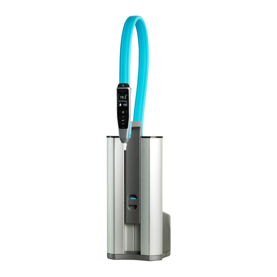
PURELAB flex
Covers the following products:
PURELAB flex 1
PURELAB flex 2
ELGA LabWater assumes that the technician using this manual has a working knowledge of
water purification systems and has attended an ELGA LabWater technical training course.
This manual is correct for use with the PURELAB range of systems mentioned above. For
information on other products from ELGA LabWater please refer to the relevant service
manual available from www.elgalabnet.net.
If you would like to contact us with regards to training or give us any feedback on this
manual please contact technical support at
techsupport@elgalabwater.com
Introduction
Issue 4
Page 1 of 45
Advertisement
Table of Contents

Subscribe to Our Youtube Channel
Related Manuals for ELGA PURELAB flex 1


Summary of Contents for ELGA PURELAB flex 1
- Page 1 PURELAB flex 1 PURELAB flex 2 ELGA LabWater assumes that the technician using this manual has a working knowledge of water purification systems and has attended an ELGA LabWater technical training course. This manual is correct for use with the PURELAB range of systems mentioned above. For information on other products from ELGA LabWater please refer to the relevant service manual available from www.elgalabnet.net.
-
Page 2: Manual Revision Notes
PF2XXXXM1 Copyright Note The information contained in this document is the property of VWS (UK) Ltd, trading as ELGA LabWater, and is supplied without liability for errors or omissions. No part of this document may be reproduced or used except as authorized by contract or other written permission from VWS (UK) Ltd. - Page 3 PURELAB flex Index Section Number / Title Sub Section Title Page Number 1 – Process Descriptions Product Specific Flow Paths Process Flow Diagrams 2 – Parts Identification Consumables Accessories Common / Basic Parts Drawings 3 – Electronics Display Icons Software History PCB Details PCB Drawings Battery Replacement...
-
Page 4: Health And Safety
Control of Substances Hazardous to Health (COSHH) Material safety data sheets covering the various replaceable Purification Packs are available upon request. If in doubt always seek advice before commencing work on ELGA products. Please contact the technical support department at techsupport@elgalabwater.com for more information. -
Page 5: Section 1 - Process Description
Section 1 – Process Description Product Specific Process Descriptions & Flow Paths flex 1 Flow Lines Inlet from pre-purified source Optional DI Pack Process Flow 1. The pre-purified water enters the system through the inlet solenoid valve and flow sensor (FS1) 2. - Page 6 PURELAB flex Flex 2 Flow Lines Inlet from Optional pre-purified DI Pack source Process Flow 1. The pre-purified water enters the system through the inlet solenoid valve and flow sensor (FS1) 2. It then passes through recirculation pump (P1), Quality sensor (QS1) and temperature sensor (TS1) 3.
- Page 7 PURELAB flex Process Flow Diagrams The Process Flow Charts are a simplified visual representation of the software routines to assist a trained technician to understand the process flow and troubleshoot symptoms. Commissioning Connect the power supply to the PURELAB flex Set Language High light correct language and...
- Page 8 PURELAB flex Sanitisation Press accept Hold down PF4 (see page 23) to access the menu V1 closes and V2 opens to release Highlight pressure from sanitisation and the system press accept Place a 1 litre Remove and container under dispose of the the dispense sanitisation pack nozzle and press...
-
Page 9: Section 2 - Parts Identification
Section 2 – Parts Identification Consumables Part Number Description LC208 Purification Pack LC210 185/254nm UV Lamp LC209 Sanitisation Pack LC197 POU Biofilter LC145 POU 0.2µ Microfilter LC211 DI Pack for LA731 Pre-conditioning kit LC197 - POU Biofilter LC210 – 185/254 UV lamp LC145 –... - Page 10 Mounting Kit Printer Though a printer can be connected to the PURELAB flex, ELGA Labwater does not supply a printer for this application. For details of recommended printers and how to configure them to work with the flex please see Product bulletin PB0011-10-Issue 1 available on our extranet site www.elgalabnet.net.
- Page 11 PURELAB flex Common / Basic Parts Below is a list of all common parts used in the PURELAB flex. Key: Not used Number of parts used Part Number Description flex 1 flex 2 ADAP32797 ADAPTOR (PARA) 8mm-3/8"BSP" BALL38832-03 UV BALLAST BOX ASSY BALL38877 BALLAST - BL 14W 24V BASE38803...
- Page 12 PURELAB flex Part Number Description Flex 1 Flex 2 PU010418 CONNECTOR 8-8MM PM0408E PUMP38824 PUMP DIAPHRAGM 88-ELG-38824 RING32087 RING O" BS115 RED SILICON" RING32088 RING O" BS119 RED SILICON" RING38850 O RING 3.5 x 1.0mm NITRILE X/S RING39086 PISTON SECURING RING RING39091 SILICONE O'RING SCRW31313...
- Page 13 PURELAB flex Drawings Please see below details of the drawings located in this section of the manual and which PURELAB flex they correspond to. Flex 1 Description Page Number MAIN BODY - EXTERNAL PARTS MAIN BODY – INTERNAL PARTS SP931 DISPENSER ARM ASSY SP921 BASE MOULDING BOTTOM SP921 BASE MOULDING TOP SP919 CARTRIDGE BULKHEAD ASSY...
- Page 14 PURELAB flex Main Body – External Parts Item Part Number Description SP964 Dispense Handset Assembly SP929 Left Hand Door SP930 Right Hand Door COVR38804 Rear Cover Section 2 – Parts Identification Issue 4 Page 14 of 45...
- Page 15 PURELAB flex Main Body – Internal Parts (flex 1 only) Item Part Number Description ADAP32797 Adaptor Straight 8mm TUBE x 3/8” BSP ELBW30903 Stem Elbow SP919 Cartridge Bulkhead Assembly SP925 Line Cell and Thermistor Assembly TUBE31957 8mm OD Clear Tube VALV37258 Non Return Valve 3/8”...
- Page 16 PURELAB flex Main Body – Internal Parts (flex 2 only) Item Part Number Description ADAP32797 Adaptor Straight 8mm TUBE x 3/8” BSP ELBW30903 Stem Elbow SP919 Cartridge Bulkhead Assembly SP923 UV Housing Assembly SP925 Line Cell and Thermistor Assembly TUBE31957 8mm OD Clear Tube VALV37258 Non Return Valve 3/8”...
- Page 17 PURELAB flex SP931 – Dispenser Arm Assembly Item Part Number Description CCAP39125 Arm Lock Cover Cap CLAM39128 Arm Clamp Ring DARM38805 Dispenser Arm HOLS38949 Holster LABL38996 Manual Retaining Label SCRW38970 M6 X 12 Machine Pan Screw SCRW39126 Arm Button Screw SCRW39209 M6 x 6 Socket Head Set Screw STUD39127...
- Page 18 PURELAB flex SP921 – Base Moulding Assembly - Bottom Item Part Number Description BUSH38879 Filter Bulkhead Bush CONN38836 8mm Short Cartridge COUP38878 Filter Bulkhead Coupling FANS38837 Fan 24v FILT36123 Stainless Steel Mesh Filter GASK38808 Base Gasket PLAT38825 Base Gland Plate PLAT38826 Base Cover Plate SP926...
- Page 19 PURELAB flex SP921 – Base Moulding Assembly - Top Item Part Number Description ELBW30903 Stem Elbow PIST38816 Cartridge Piston PUMP38824 Recirculation Pump RING39091 O-Ring SPRG38843 Compression Spring Section 2 – Parts Identification Issue 4 Page 19 of 45...
- Page 20 PURELAB flex SP923 – UV Housing Assembly Item Part Number Description BALL38832 UV Ballast Box BALL38877 UV Ballast CAPS32084 Threaded Cap DISC32086 Lamp Sealing Disk FANS38837 Fan 24v HOUS38855 UV Housing PU010418 Adaptor Equal 8mm OD RING32087 O Ring BS115 RING32088 O Ring BS119 SP925...
- Page 21 PURELAB flex SP919 – Cartridge Bulk Head Assembly Item Part Number Description BULK38818 Cartridge Bulkhead Fitting CONN38836 8mm Short Cartridge Connector Section 2 – Parts Identification Issue 4 Page 21 of 45...
- Page 22 PURELAB flex SP926 – Flow Sensor Assembly Item Part Number Description ADAP38858 Adaptor RING38867 O Ring BS013 SENS37219 Sensor Flow 3/8” Male Ports Section 2 – Parts Identification Issue 4 Page 22 of 45...
-
Page 23: Section 3 - Electronics
Section 3 - Electronics Display Icons Dispense Button Auto Volume Dispense Accept Down Quality Display This shows the outlet quality in MΩ or µS. Please be aware MΩ can only be read when the optional DI pack is Info Bar installed This scrolling info bar shows:... -
Page 24: Software History
Please find below details of the part numbers for these boards and where they are used. PURELAB flex Product type PCB Part Number PURELAB flex 1 PCBS38875 PURELAB flex 2 PCBS38875 Software Installation Instructions The PCB part numbers above are for blank boards and will need software installing on them when initially installed. - Page 25 PURELAB PURELAB flex flex 1 Section 3 - Electronics Issue 4 Page 25 of 45...
- Page 26 PURELAB PURELAB flex flex 2 Section 3 - Electronics Issue 4 Page 26 of 45...
- Page 27 PURELAB flex Dispense Handset Recirculation Pump Quality Line Cell Inlet Solenoid Valve Not Used UV Ballast TH5A UV and Base Fan Temperature Sensor Power Supply Flow Sensor Not Used Data Tag – Pins 5 & 6 Foot Switch – Pins 7 & 8 FUSE39145 –...
-
Page 28: Battery Replacement Instructions
PURELAB flex Battery Replacement The PCB boards used on the PURELAB flex have a battery installed on them to maintain the settings when the system is powered down. If the battery needs to be replaced please be aware that all of the user settings and timers will be lost and will need to be reset once the new battery is installed. -
Page 29: Electrical Parameters
PURELAB flex Electrical Parameters Most ELGA products are powered from a mains electrical supply, this could be up to 240V. Please ensure that when performing maintenance on these units that the power supply is isolated whenever possible before any work is carried out. -
Page 30: Section 4 - Maintenance
Service Recommendations This document is designed to help guide you through the component and system checks recommended by ELGA LabWater. Detailed below are some recommended checks that should be performed during a routine service visit. When arriving on site a risk assessment must be completed prior to any work being undertaken to ensure your safety. -
Page 31: Operational Parameters
PURELAB flex Operational Parameters The operational parameters detailed in this section of the manual are to be used in conjunction with the service recommendations. Inlet Pressure Adjustment During Commissioning Install the pressure regulator between the pre- Feed Feed purified water source and the PURELAB flex (fig Water to flex Ensure that the pressure regulator is installed in... - Page 32 The main power will be on while performing the calibration procedure, please use caution It is good practice to calibrate the system every 12 months. This must be carried out by an ELGA trained service technician using the correct substitution (sub) boxes.
- Page 33 PURELAB flex Sub Box Connection to Adaptor SUB-07 SUB-15 SUB-14 SUB-07 μS/cm MΩ.cm Calibration Calibration Calibration Calibration Position Position Position Position Feed Water Resistivity Quality Cell Used for validation Purposes Temperature SUB Box Adaptor – to JH3 on PCB Only Quality SUB Box Adaptor –...
- Page 34 PURELAB flex Calibration Process Tables Quality and Temperature Sensor Calibration Action Sub Box Value Insert the prepared USB stick into the USB port on the right hand side of the PURELAB flex The USB menu will be displayed Scroll through the menu using the Up or Down buttons (PF3 & PF5) Once Service Calibration is highlighted press Accept (PF4) to access the calibration procedure Skip outlet valve adjustment?
- Page 35 PURELAB flex Action Sub Box Value Set sub box to the required value and wait for the display value to settle and turn white. SUB Box 15 Press Accept (PF4) to save the setting Press Auto Volume dispense (PF2) to move on to the next screen Press Up (PF3) to accept the calibration and move on to the next section or press Down (PF5) to repeat the previous...
-
Page 36: Sanitization Chemicals
PURELAB flex Sanitisation Sanitization Chemicals During the sanitization of our products you may be required to handle chemicals such as Chlorine or Hydrogen Peroxide. Care should be taken to ensure the safety of yourself and others around you while using these chemicals. A material safety data sheet conforming to COSHH regulations is provided with the chemical, please read this carefully before carrying out the sanitization. -
Page 37: Section 5 - Specifications
Section 5 - Specifications System Specifications Treated Water Specifications PURELAB flex PURELAB flex PURELAB flex (with purification (with UV and pack) purification pack) Delivery flow rate Up to 2 l/min (maximum) Inorganics (resistivity As per feedwater 18.2 MΩ-cm 18.2 MΩ-cm @25°C) Organics (TOC) –... - Page 38 PURELAB flex Feedwater Requirements PURELAB flex PURELAB flex PURELAB flex (with purification (with UV and pack) purification pack) Originally from potable supply, then pre treated. Preferably reverse Source osmosis (RO), filtered service deionization (SDI) or distilled. Conductivity <1 µs/cm Free chlorine <0.05 ppm Carbon dioxide <0.1 ppm...
-
Page 39: Section 6 - Troubleshooting
Section 6 - Troubleshooting Symptom Possible Cause Check water supply is on. Ensure pressure regulator is open and set to a Max of 1.5 Bar No water coming from dispense nozzle Confirm voltage to pump Confirm inlet solenoid functional Clean inlet strainer Confirm the power supply is connected to the No display mains power in... -
Page 40: Section 7 - Appendix
Section 7 - Appendix Appendix Index Appendix Description Page Number Commissioning Report Routine Service Report Calibration Certificate Service Bulletin Section 7 – Appendix Issue 4 Page 40 of 45... -
Page 41: System Settings
Flooded Suction 1.5 bar (21 psi) Consumables Installed Date Comments DI Pack UV Lamp I confirm that the above commissioning was carried out by an ELGA Labwater Trained Representative. Signed..........Date........ Section 7 - Appendix Issue 4 Page 41 of 45... - Page 42 PURELAB flex Appendix B Routine Service Report Site History and Observations: General Questions - Site Related Concerns? Review Service History Review Customer's Operation Log Query lab manager/users about unit's operation VISUAL Check of unit's location/connections Corrected? Is the unit clear of obstruction? Is there space for the front doors to open fully and still have space to service the unit? Is there clear access to feed water shut-off valve?
- Page 43 Consumable Change Consumables Changed Comments DI Pack UV Lamp Quartz Thimble & O-Rings I confirm that the above commissioning was carried out by an ELGA Labwater Trained Representative. Signed..........Date........ Section 7 - Appendix Issue 4 Page 43 of 45...
-
Page 44: Calibration Certificate
JH2 (using adaptor) Sub Box 07 JH3 (using adaptor) Sub Box 07 JH3 (using adaptor) I confirm that the above calibration was carried out by an ELGA Labwater Trained Representative. Signed..........Date......... Section 7 - Appendix Issue 4 Page 44 of 45... - Page 45 For further information and technical details on all ELGA LabWater products please contact Technical Support at: ELGA LabWater Global Operations Lane End Industrial Park High Wycombe Bucks HP14 3BY Phone - +44 (0) 1494 887850 Fax - +44 (0) 1494 887505 Email –...
- Page 46 Service Bulletin – LWGSBN0086 PURELAB flex Guidelines As a result of site feedback on the PURELAB flex, we have produced these guidelines to circulate some of the most frequently requested information that is currently not available in the service or operators manual. All of the information in this bulletin is correct as per version 1.2.1 of the PURELAB flex software.
-
Page 47: Button Combinations
Service Bulletin – LWGSBN0086 Button Combinations There are many different button combinations that can Dispense be used to access certain Button functions on the PURELAB flex. Below are details of these combinations and their functions. We have numbered the buttons for ease of use, please Auto see the diagram on the right Volume... - Page 48 Service Bulletin – LWGSBN0086 Calibration of Outlet Valve Action Insert a USB stick containing the SERVICE.TST calibration file into the USB port on the right hand side of the PURELAB flex. The USB menu will be displayed. Scroll through the menu using the Up or Down buttons (PF3 &...
- Page 49 Service Bulletin – LWGSBN0086 Instructions for changing the dispense Handset SP964 – PURELAB flex 1 & 2 Isolate the power to the PURELAB flex. Remove the back cover and undo the 4 screws from the top panel. The back cover can then be removed.
- Page 50 Service Bulletin – LWGSBN0086 Return the board to it’s default settings and reinstall the software as per the below instructions: Power down the PURELAB flex. Press the [Down key PF5] and [Auto Volume Dispense key PF2]. Power up the PURELAB flex. Wait a few minutes until the Controller starts re-programming itself, do not let go of the buttons.
- Page 51 Choose the correct model and press accept: TOC System – PURELAB flex 2 Basic System – PURELAB flex 1 RO System – PURELAB flex 3 Direct Feed System – PURELAB flex 4 Select the below options to exit the test procedure: Skip Service Calibration? Select No and press accept, calibrate the system as per the instructions in the service manual.
- Page 52 Loosen the 2 side retaining screws on the reservoir. Unplug the gun from the PCB (TH1). Lay the PURELAB flex on it‟s side with the ELGA label uppermost and disconnect the tubing at the line cell and non return valve to release the gun.
- Page 53 Service Bulletin – LWGSBN0086 The dispense gun can now be removed from the PURELAB flex, ensuring that you retain the black top plate. Install the new dispense gun and reassemble the PURELAB flex. Return the board to it’s default settings and reinstall the software as per the below instructions: Power down the PURELAB flex.
- Page 54 The screen will list the types of system available. Choose the correct model and press accept. TOC System – PURELAB flex 2 Basic System – PURELAB flex 1 RO System – PURELAB flex 3 Direct Feed System – PURELAB flex 4...
- Page 55 Manager) 2011 Approved by (Head of Technical April Name: M White Date: Support) 2011 ELGA is the global laboratory water brand name of Veolia Water Solutions & Technologies. CENTRA®, PURELAB®, MEDICA®, PURESURE® are all ELGA trademarks. Page 10 of 10...
Need help?
Do you have a question about the PURELAB flex 1 and is the answer not in the manual?
Questions and answers