Table of Contents
Advertisement
Quick Links
Advertisement
Table of Contents

Subscribe to Our Youtube Channel
Related Manuals for Toshiba RAV-SM182CTP-UL


Summary of Contents for Toshiba RAV-SM182CTP-UL
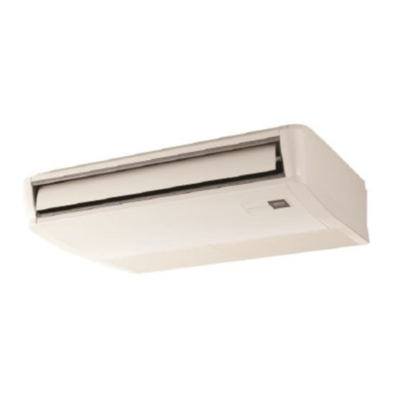
- Page 1 1115652713-1 AIR CONDITIONER (SPLIT TYPE) Installation Manual Indoor Unit For commercial use Pour usage commercial Model name: Para uso comercial Ceiling Type RAV-SM182CTP-UL RAV-SM242CTP-UL RAV-SM302CTP-UL RAV-SM362CTP-UL RAV-SM422CTP-UL RAV-SM482CTP-UL Installation Manual English...
-
Page 2: Table Of Contents
� 1 � Contents Original instruction Please read this Installation Manual carefully before installing the Air Conditioner. 1 Precautions for safety ....................3 • This Manual describes the installation method of the indoor unit. • For installation of the outdoor unit, follow the Installation Manual attached to the outdoor unit. 2 Accessory parts ...................... - Page 3 Electrical-related work Insulating shoes made by Toshiba Carrier Corporation. He or she has been trained to install, maintain, relocate and Clothing to provide protection from electric shock remove the air conditioners made by Toshiba Carrier Corporation. or, alternatively, he or she has...
-
Page 4: Precautions For Safety
� 3 � ■ Warning indications on the air conditioner unit Precautions for safety The manufacturer shall not assume any liability for the damage Warning indication Description caused by not observing the description of this manual. WARNING WARNING WARNING ELECTRICAL SHOCK HAZARD Disconnect all remote ELECTRICAL SHOCK HAZARD electric power supplies... - Page 5 • Do not touch the aluminium fin of the unit. You may injure Selection of installation location yourself if you do so. If the fin must be touched for some reason, • When the air conditioner is installed in a small room, provide first put on protective gloves and safety work clothing, and then appropriate measures to ensure that the concentration of proceed.
- Page 6 � 5 � Refrigerant piping • Incomplete grounding causes an electric shock. • Do not connect grounding wires to gas pipes, water pipes, and • Install the refrigerant pipe securely during the installation work lightning conductor or telephone earth wires. before operating the air conditioner.
- Page 7 • After the work has finished, use an insulation tester set CAUTION (500V Megger) to check the resistance is 1MΩ or more between New refrigerant air conditioner installation the charge section and the non-charge metal section (Earth/Ground • This air conditioner adopts the new HFC refrigerant (R410A) section).
-
Page 8: Accessory Parts
� 7 � Selection of installation place Accessory parts Avoid installing in the following places. Part name Q’ty Shape Usage Select a location for the indoor unit where the cool or warm air will circulate evenly. Installation Manual This manual (Hand over to customers) Avoid installation in the following kinds of locations. -
Page 9: Installation
Installation Installation space (Unit: in (mm)) Reserve sufficient space required for installation or service work. CAUTION Strictly comply with the following rules to prevent damage of the indoor units and human injury. 9.8" (250) 9.8" (250) • Do not put a heavy article on the indoor unit or let a person get on it. (Even units are packaged) or more or more •... - Page 10 � 9 � Installation of hanging bolt Before installation Installation of hanging bolt CAUTION Use W3/8 (M10) hanging bolts (4 pcs, locally procured). • When determining the location of the indoor unit, Removal of air intake grille Matching to the existing structure, set pitch according consider the piping and wiring connections.
- Page 11 Draw-out direction of pipe / Installation of indoor unit <In case of taking pipe from upper side> Holding down of main unit wire Taking pipe from upper side is applied only to the refrigerant pipe. <Hanging the indoor unit directly from the ...
- Page 12 � 11 � Attaching the hanging bracket Installation of electrical cover 2 holes type Attach the indoor unit onto the hanging first bracket and fasten it tight with the bolts and screws. REQUIREMENT Remove the screws fastening hanging bracket •...
-
Page 13: Drain Piping
Connection of drain hose Drain piping • Insert the attached drain hose into the drain pipe connecting port on the drain pan up to the end. • Fit the attached hose band to the end of the pipe connecting port, and then tighten it securely. CAUTION REQUIREMENT Following the Installation Manual, perform the drain piping work so that water is properly drained. -
Page 14: Refrigerant Piping
� 13 � Evacuation * In case of flaring for R410A with the conventional Refrigerant piping Connecting refrigerant piping flare tool, pull it out approx. 0.02" (0.5 mm) more than that for R22 to adjust to the specified flare size. The Perform vacuuming from the charge port of valve of copper pipe gauge is useful for adjusting projection the outdoor unit by using a vacuum pump. -
Page 15: Electrical Connection
Heat insulation process Electrical connection Apply heat insulation for the pipes separately at liquid side and gas side. • For the heat insulation to the pipes at gas side, use the material with heat-resisting temperature WARNING 248°F (120°C) or higher. •... - Page 16 � 15 � Wiring between indoor unit and outdoor unit Wire connection • Figure below shows the wiring connections between the indoor and outdoor units and between the indoor units REQUIREMENT and remote controller. The wires indicated by the broken lines or dot-and-dash lines are provided at the locally. •...
-
Page 17: Applicable Controls
Applicable controls <Multi-indoor-unit connection> Basic procedure for REQUIREMENT changing settings Power supply wiring for It takes some time before the remote control multiple indoor units becomes operable when the remote control is used for the first time. This is not a malfunction. Change the settings while the air conditioner is not working. - Page 18 � 17 � DN setting Installing indoor unit on high Filter sign setting Energy saving ceiling Perform the advanced settings for the air conditioner. Set for the energy saving operation: Energy saving According to the installation condition, the filter sign Carry out the setting operation while the indoor unit term (Notification of filter cleaning) can be changed.
- Page 19 Energy saving operation Push the [ MENU] button. Indoor unit data Setting” appears on the screen, then the “ Set for the power saving operation of the air conditioner. screen returns to the “Energy saving CODE No. Data name operation”...
- Page 20 � 19 � Group control Group control for system of multiple units One remote controller can control maximum 8 indoor units as a group. Simultaneous twin, triple or double twin system Group control in single system A combination with an outdoor unit allows simultaneous ON / OFF operation of the indoor units. The following system patterns are available.
- Page 21 [Procedure example] Indoor UNIT No. before setup change is displayed. Push the “ unit” [ F1] button to select the unit to set. Manual address setup procedure The selected unit changes as follows each While the operation stops, change the setup. time the button is pushed: (Stop the operation of the unit.) Push the “...
-
Page 22: Test Run
� 21 � Test run 46 °F (8 °C) operation After check of the changed contents, Push the “ No” [ F2] button to Before test run finish the setting operation. “ Setting” Pre-heating operation can be set for cold regions appears on the screen for a while, then the where room temperature drops to below zero. -
Page 23: Maintenance
Maintenance Wireless remote controller Checking remote transmission 1. Push the ON/OFF button on the remote controller to determine that it works properly. NOTE <Daily maintenance> Cleaning with water or vacuum cleaner. • Pushing the TEMPORARY button once (for about • Be sure to operate the unit, following the instruction •... -
Page 24: Troubleshooting
� 23 � Troubleshooting Periodic Maintenance • For environmental conservation, it is strongly recommended that the indoor and outdoor units of the air conditioner in use be cleaned and maintained regularly to ensure efficient operation of the air conditioner. ... - Page 25 Error codes and parts to be checked Wired Wireless remote controller remote Sensor block display of controller receiving unit Judging Wired display Main defective parts Parts to be checked / error description conditioner Wireless remote controller device remote Operation Timer status Sensor block display of controller...
- Page 26 � 25 � Wired Wireless remote controller remote Sensor block display of controller receiving unit Judging display Main defective parts Parts to be checked / error description conditioner device Operation Timer status Indication Ready Flashing GR GR OR Indoor fan motor, indoor P.C. board --- Indoor AC Indoor unit fan error Indoor fan error (fan motor thermal relay activated) was...
- Page 27 Warnings on Refrigerant Leakage Important Check of Concentration Limit The room in which the air conditioner is to be installed requires a design that in the event of refrigerant 2) When there is an effective opening with the adjacent room for ventilation of leaking refrigerant gas (opening gas leaking out, its concentration will not exceed a set limit.
- Page 28 144 / 9 Moo 5, Bangkadi Industrial Park, Tivanon Road, Tambol Bangkadi, Amphur Muang, Pathumthani 12000, Thailand 1115652713-1...
Need help?
Do you have a question about the RAV-SM182CTP-UL and is the answer not in the manual?
Questions and answers