Advertisement
Quick Links
Packing List
In addition to this guide, the package includes the following items:
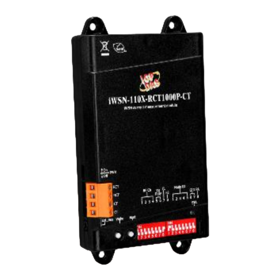
iWSN-110X-RCT Series
Module
Module Name
iWSN-110X-RCT1000P-CT
iWSN-110X-RCT1000PL-CT
Technical Support
service@icpdas.com
www.icpdas.com
For Desktop Web
iWSN-110X-RCT Series Quick Start
Split-core CT
Split-core CT
8m, Φ24mm (200A), 1 pcs
8m, Φ36mm (400A), 1 pcs
Resources
How to search for drivers, manuals and spec
information on ICP DAS website.
For Mobile Web
iWSN-110X-RCT
iWSN-110X-RCT
v1.0, February 2022
Rogowski Coil
(RCT)
Rogowski Coil (RCT)
4m, Φ80mm (1000A), 1 pcs
Screw Driver (1C016)
P1
Advertisement

Related Manuals for ICP DAS USA iWSN-110X-RCT Series


Summary of Contents for ICP DAS USA iWSN-110X-RCT Series
- Page 1 Series Quick Start v1.0, February 2022 Packing List In addition to this guide, the package includes the following items: iWSN-110X-RCT Series Split-core CT Rogowski Coil Screw Driver (1C016) Module (RCT) Module Name Split-core CT Rogowski Coil (RCT) iWSN-110X-RCT1000P-CT 8m, Φ24mm (200A), 1 pcs 4m, Φ80mm (1000A), 1 pcs...
- Page 2 Warning ICP DAS assumes no liability for any damage resulting from the use of this product. ICP DAS reserves the right to change this manual at any time without notice. The information furnished by ICP DAS is believed to be accurate and reliable.
- Page 3 Wire and Buttons Switch Instructions Power on Power off Name Instructions Rogowski Coil (RCT) pin, no directionality, support measuring function Split-core CT pin, no directionality, support charging function Extension bus Instructions Empty or connect Ext_Bus extension module Button Instructions Wake Manual wake up After pressing for 1~3 seconds, the Boot...
-
Page 4: Communication Parameter
Communication parameter Name Instructions Reserved TX Duty Period ( RF transmit duty ) □ □ 1 sec ■ □ ■: ON 10 sec □ ■ 30 sec □: OFF ■ ■ 60 sec RF Ch □ □ □ □ □ □... - Page 5 Name Instructions Factory Only Group (Group ID) □ □ ■ □ ■: ON □ ■ □: OFF ■ ■ Node Node □ □ □ □ □ □ □ □ □ ■ ■ □ □ □ □ ■ □ □ □ ■...
-
Page 6: Led Indicator
LED indicator The module provides one LED indicator. The table below will show the LED status. Indicators Status Instructions 500ms Illegal Node ID, please set the Node ID Blink to 1~31, and then power on. continuous Low battery power. 1. Please confirm whether the CT is lock into the “CT”... - Page 7 Boot Steps ○ ○ ○ ○ A. Please confirm the CT and Rogowski Coil (RCT) are locked into the module, and “Ext_Bus” is connected an extension module by audio line. (If there is no extension module, the “Ext_Bus” don’t be connected.) B.
- Page 8 CT or equipment connected in the secondary circuit. 2. The external CT’s are fragile, please handle with care. 3. The current input of the iWSN-110X-RCT series only supports the factory-attached CT. 4. To install CT’s correctly, please ensure the CT lines sequences is right before clip the CT’s onto the power cable of the monitoring equipment.