Cobra 29 LTD CLASSIC Manual
- How to use manual (46 pages) ,
- Owner's manual (22 pages) ,
- User manual (21 pages)
Advertisement
- 1 Features of This Product
- 2 The CB Story
- 3 Controls and Indicators
- 4 Customer Support
- 5 Installation
- 6 Antennas
-
7
Operation
- 7.1 Turning On
- 7.2 Setting Channel Selector
- 7.3 Calibrate for SWR (Standing Wave Ratio)
- 7.4 To Receive
- 7.5 Selecting A Channel
- 7.6 S-Meter
- 7.7 NB-ANL/ANL/OFF (Noise Blanker/Automatic Noise Limiter) Switch
- 7.8 Bright/Dim Switch
- 7.9 RF Gain Control
- 7.10 Setting Delta-Tune
- 7.11 Setting Squelch
- 7.12 To Transmit
- 7.13 Setting Dynamike
- 7.14 Transmit
- 7.15 RF Meter
- 7.16 External Speaker
- 7.17 PA (Public Address)
- 7.18 Home And Office Set-Up
- 7.19 Temporary Mobile Set-Up
- 8 How Your CB Can Serve You
- 9 Frequency Ranges
- 10 29 LTD Classic Specifications
- 11 FCC Statement
- 12 Limited Two Year Warranty
- 13 Product Service
- 14 Ordering Info
- 15 Videos
- 16 Documents / Resources
Features of This Product
- 40 CB Radio Channels
- Heavy-Duty Dynamic Microphone
- Full 4 Watts AM RF Power Output
- SWR Calibration
- Instant Channel 9/19
- 4-Pin Front Mount Microphone Connector
- Delta -Tune
- Switchable Automatic Noise Limiter & Noise Blanker
- Adjustable Dynamike® Boost
- 9 Ft. Mic Cord
- RF Gain
The CB Story
The Citizens Band lies between the shortwave broadcast and 10-meter Amateur radio bands, and was established by law in 1949. The Class D two-way communications service was opened in 1959. (CB also includes a Class A citizens band and Class C remote control frequencies.)
Federal Communications FCC Regulations
FCC regulations permit only "transmissions" (one party to another) rather than "broadcasts" (to a wide audience). Thus, advertising is not allowed on CB Channels because that is "broadcasting."
FCC Warnings
All transmitter adjustments other than those supplied by the manufacturer as front panel operating controls, must be made by, or under the supervision of, the holder of an FCC-issued general Radio-Telephone Operator's License.
Replacement or substitution of transistors, regular diodes or other parts of a unique nature, with parts other than those recommended by Cobra, may cause violation of the technical regulations of Part 95 of the FCC Rules, or violation of Type Acceptance requirements of Part 2 of the Rules.
What's Included with Your 29 LTD Classic

- CB Transceiver
- Microphone
- Transceiver Bracket
- Microphone Bracket
- DC Power Cord
- Operating Manual
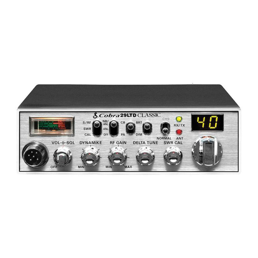
Controls and Indicators

- 4-Pin Microphone Connector
- Power On/Off/Volume/ Squelch Control
- Dynamike®
- RF Gain
- Delta-Tune
- SWR CAL
- Channel Selector
- LED Channel Display
- ANT LED Indicator
- RX (Receive)/TX (Transmit) LED Indicator
- Channel 9/19/Normal Switch
- Bright/Dim Switch
- CB/PA Switch
- NB/ANL ANL Off Switch
- S/RF SWR CAL Switch
- Signal Strength Meter
- Microphone
Back Side
- Public Address Speaker Jack
- External Speaker Jack
- Antenna Connector
- Power Jack
Customer Support
Should you encounter any problems with the product or not understand its many features, please refer to this owner's manual. If, after referring to the manual, you still need help, call Cobra Customer Service at 800-543-1608.
Cobra Assistance
Should you encounter any problems with this product, or not understand its many features, please refer to this owner's manual. If you require further assistance after reading this manual, Cobra Electronics offers the following customer assistance services:
Monday-Friday 9:00 AM- 5:00 PM EST
Call: 800-543-1608
SERVICE
Monday-Thursday 9:00AM-5:00PM EST
Call: 800-543-1608
Office:
6500 West Cortland Street, Chicago, IL, 60707
Have questions? We can help.
Contact us at 800-543-1608 M-F 9:00AM-5PM EST
For Assistance Outside the U.S.A.
Contact Your Local Dealer
Installation
Location
Plan location of transceiver and microphone bracket before starting the installation.
Select a location that is convenient for operation, yet does not interfere with the driver or passenger.
The transceiver is usually mounted to the underside of the dash with the microphone bracket beside it.
Mounting and Connection
- Hold the radio with the mounting bracket in the exact desired location. If there is no interference, remove the bracket and use it as a template to mark the location for the mounting screws.

- Drill the holes and secure the bracket.

- Connect the antenna cable plug to the receptacle marked "ANT" on the back of the unit.

- Connect the red lead of the DC power cord to the positive post of the battery or to an accessory 12 volt fuse.
- Connect the black lead to the of the DC power cord to the negative post of the battery or to the vehicle chassis.

- Plug the power cord into the jack marked "Power" on the back of the unit. Be sure to observe polarity markings.
- Mount the microphone bracket on either side of the radio (driver's left) using the two supplied screws. Bracket should be placed under the dash so the microphone is readily accessible.


- Attach the 4-pin microphone cable to the connector on the front of the radio and install the microphone on bracket securely.


Notes
The transceiver is held in the universal mounting bracket by two thumbscrews which allow for adjustment at a convenient angle.
The bracket includes two self-tapping screws and star washers. The mounting must be mechanically strong, conveniently located.
For best performance, we recommend the radio be connected directly to the battery.
Before installing the CB radio, visually check the vehicle's battery connection to determine which terminal is positive or negative. A negatively grounded vehicle has its negative lead grounded to the chassis.
Connecting to an accessory fuse prevents the unit from being left on accidentally, and also permits operating the unit without running the engine.
If the microphone is not connected, audio will not be heard at the speaker.
Antennas
CB Antenna
Since the maximum allowable power output of the transmitter is limited by the FCC, the antenna is critical in affecting transmission distance. Only a properly matched antenna system will allow maximum power output. Cobra loaded type antenna models are highly recommended for most installations. Consult your Cobra dealer for further details, or visit our website: www.cobra.com
- A standard antenna connector is provided on the transceiver for easy connection.


Marine Installation
The transceiver will not operate at maximum efficiency in a boat without a ground plate, (unless it has a steel hull). Before attempting installation, consult your dealer for information regarding an adequate grounding system and prevention of electrolysis between fittings in the hull and water.
Use of a mobile receiver at low signal levels is normally limited by the presence of electrical noise. The primary source of noise in automobiles is from the alternator and ignition system. Typically, when signal level is adequate, the background noise does not present a serious problem. Also, when extremely low level signals are being received, the transceiver may be operated with the vehicle's engine turned off. The unit requires very little current and therefore will not significantly discharge the vehicle's battery.
Even though the Cobra 29 LTD Classic has an automatic noise limiter, in some installations ignition interference may be high enough to make good communications impossible. Many possibilities exist and variations between vehicles require different solutions. Consult your COBRA dealer or a 2-way radio technician for help in locating the source of a severe noise.
Notes
For optimum performance in passenger cars the ideal antenna location is on the center of the roof. Second choice is on the center of the trunk.
Because many newer trucks feature fiberglass door skins, the outside mirror must be grounded to the chassis via a ground strap when antenna is mounted on the mirror bracket.
3-way Combination Antennas are also available which allow operation of all three bands (AM-FM & CB), using a single antenna. However, this type of antenna usually results in less than normal transmit and receive range when compared to a standard-type "Single Band" CB antenna.
Operation
Turning On
Make sure the power cord, antenna and microphone are connected to their proper connectors before starting.
- The
![]() CB/PA button should be in the CB position.
CB/PA button should be in the CB position.
- Rotate the On/Off Volume knob
![]() clockwise to a normal listening level.
clockwise to a normal listening level.

 clockwise to a normal listening level.
Setting Channel Selector

- Set
![]() the CH9/CH19/NOR switch to NOR.
the CH9/CH19/NOR switch to NOR. - Select
![]() one of forty channels and adjust the volume. The selected channel is indicated by the LED readout directly above the channel selector knob.
one of forty channels and adjust the volume. The selected channel is indicated by the LED readout directly above the channel selector knob.
 the CH9/CH19/NOR switch to NOR.
  one of forty channels and adjust the volume. The selected channel is indicated by the LED readout directly above the channel selector knob.
Calibrate for SWR (Standing Wave Ratio)
SWR meter calibration is required to accurately measure the SWR of the connected antenna system. Careful adjustment is critical to obtain best accuracy.
- Select
![]() channel 20.
channel 20. Step 1")
- Switch to the
![]() CAL position.
CAL position. Step 2")
- Push and hold the mic button.
 Step 3")
- While holding the mic button adjust the
![]() SWR CAL knob so the meter needle swings to the CAL ▼ mark on the right side of the meter.
SWR CAL knob so the meter needle swings to the CAL ▼ mark on the right side of the meter. Step 4")
 Step 5")
- While still holding down the mic button, set the S/RF SWR CAL switch to the SWR position, to read the SWR reading.
 Step 6")
- Repeat the same steps two through five on Channel 1 and 40. This will check SWR for all channels.
 Step 1")
 Step 2")
 Step 3")
 SWR CAL knob so the meter needle swings to the CAL ▼ mark on the right side of the meter.
 Step 4")
 Step 5")
 Step 6")
Notes
Antenna Indicator LED will illuminate RED when transmitting if the SWR is high.
Calibration must be made in an open area (never in a garage). Vehicle doors must be closed. No one should be standing near the antenna. (See your antenna directions for more complete information).
The reading will be slightly higher on Channels 1 and 40 compared to Channel 20.
When switched to SWR position the meter needle should ideally be as far to the left as possible. Anything over 3 is not acceptable. The antenna indicator will light. A slight antenna height adjustment (higher or lower) may be required. Repeat recalibration steps.
To Receive
- Rotate the
![]() On/Off Volume knob clockwise. The green RX/TX LED will be illuminated.
On/Off Volume knob clockwise. The green RX/TX LED will be illuminated.

Selecting A Channel

- Switch to
![]() NORMAL to select a desired channel.
NORMAL to select a desired channel. - Select
![]() one of forty channels.
one of forty channels.
S-Meter
Swings proportionately to the strength of an incoming signal when receiving.

- The
![]() S/RF-SWR-CAL switch must be in the S/RF position to read the meter.
S/RF-SWR-CAL switch must be in the S/RF position to read the meter.
NB-ANL/ANL/OFF (Noise Blanker/Automatic Noise Limiter) Switch
 Switch")
- When switched to
![]() ANL the Automatic Noise Limiter is activated. This helps reduce noise created by the vehicle's electronics.
ANL the Automatic Noise Limiter is activated. This helps reduce noise created by the vehicle's electronics.
When switched to![]() NB/ANL position the RF Noise Blanker is also activated, providing increased noise filtration.
NB/ANL position the RF Noise Blanker is also activated, providing increased noise filtration.
When switched to![]() OFF position all noise filtration will be turned off.
OFF position all noise filtration will be turned off.
 ANL the Automatic Noise Limiter is activated. This helps reduce noise created by the vehicle's electronics.
Note
The RF noise blanker is very effective in reducing repetitive noises such as ignition interference.
Bright/Dim Switch

- Switch to
![]() BRT or DIM to control the brightness of the channel indicator and multi-function meter for day or nighttime driving.
BRT or DIM to control the brightness of the channel indicator and multi-function meter for day or nighttime driving.
RF Gain Control
The RF Gain is used to optimize the reception in strong or weak signal areas.

- Rotate the
![]() RF Gain knob counterclockwise to reduce gain in strong signal areas. In weak signal areas turn clockwise to increase the gain.
RF Gain knob counterclockwise to reduce gain in strong signal areas. In weak signal areas turn clockwise to increase the gain.
Setting Delta-Tune
Delta-Tune functions as a "fine tune" control enabling you to capture a more readable signal, as well as eliminate adjacent channel interference.

- Rotate
![]() Delta-Tune knob to the center position for optimum tuning.
Delta-Tune knob to the center position for optimum tuning.
Setting Squelch
Squelch is the "control gate" for incoming signals.
- Full
![]() clockwise rotation closes the gate allowing only very strong signals to enter.
clockwise rotation closes the gate allowing only very strong signals to enter.

- Full
![]() counterclockwise rotation opens the "gate" allowing all signals in.
counterclockwise rotation opens the "gate" allowing all signals in.

- To achieve the Desired Squelch Setting (DSS), turn the Squelch control
![]() counterclockwise until you hear noise. Now turn the control clockwise just until the noise stops. This is the DSS setting.
counterclockwise until you hear noise. Now turn the control clockwise just until the noise stops. This is the DSS setting.

 clockwise rotation closes the gate allowing only very strong signals to enter.

 counterclockwise rotation opens the "gate" allowing all signals in.

 counterclockwise until you hear noise. Now turn the control clockwise just until the noise stops. This is the DSS setting.

To Transmit

- Select desired
![]() channel.
channel.

Be sure the antenna is properly connected to the radio before transmitting. Prolonged transmitting without an antenna, or a poorly matched antenna, could cause damage to the transmitter.
Be sure to read the F.C.C. Rules and Regulations before transmitting.
Setting Dynamike®
This controls the microphone sensitivity (outgoing audio level).

- Initially, set fully
![]() clockwise so that maximum voice volume is available. Dynamike® may have to be reduced in some conditions.
clockwise so that maximum voice volume is available. Dynamike® may have to be reduced in some conditions.
Transmit

- Push and hold the mic button to transmit. The transmitter is now activated. When transmitting, hold the microphone two inches from your mouth and speak in a clear, normal voice. Release to receive.
RF Meter
This meter swings proportionately to the RF output (outgoing signal) while transmitting.

The  S/RF-SWR-CAL switch must be in the S/RF position.
External Speaker
The external speaker jack is used for remote receiver monitoring.

Connect an external speaker to the external speaker jack on the rear panel.
Notes
The external speaker should have 8-ohm impedance and be rated to handle at least 4.0 Watts. When the external speaker is plugged in, the internal speaker is automatically disconnected. To order external speakers and other accessories, please go to www.cobra.com
Cobra external speakers are rated at 10 Watts.
PA (Public Address)
- Connect an external PA speaker to the PA jack on the rear panel.
 Step 1")
- Set
![]() CB/PA switch to PA position.
CB/PA switch to PA position. Step 2")
- Push and hold the microphone button and speak in a normal voice. Your voice will be heard on the PA speaker.
 Step 3")
- Adjust the PA speaker volume with the
![]() Dynamike® control.
Dynamike® control. Step 4")
 Step 1")
 Step 2")
 Step 3")
 Step 4")
Notes
The PA speaker should have 8-ohm impedance and be rated to handle at least 4.0 Watts.
The speaker should be directed away from the microphone to prevent acoustic feedback.
Activity on the CB channel will be heard through the PA speaker. Adjust the volume control to a normal listening level.
Home And Office Set-Up
Base Station Operation (From 120V AC House Current)
To operate the transceiver from your home or office you will need a 13.8 Volt DC Power Supply rated at a minimum of 2 amps and a properly installed base station antenna.
- Simply connect the red (+) and black (-) leads of the transceiver to the corresponding terminals of the power pack.
 Step 1")
- Plug the power cable into the jack marked "Power" on the back of the unit. Be sure to observe polarity markings.
 Step 2")
- Connect a properly installed and matched base station antenna.
 Step 1")
 Step 2")

Do not attempt to operate this transceiver by connecting it directly to 120V AC.
Temporary Mobile Set-Up
Temporary Mobile Operation
For temporary mobile operation you may want to purchase an optional automobile power adapter. This adapter and a magnetic mount antenna allow you to quickly "install" your transceiver for temporary use.

How Your CB Can Serve You
- Warn of traffic problems
- Provide weather and road data
- Provide help in event of an emergency
- Provide direct contact with home or office
- Assist police by reporting erratic drivers
- Get "local information" to find a destination
- Communicate with family and friends
- Suggest spots to eat and sleep
- Keep you alert while traveling
A Few Rules You Should Know
- Conversations cannot last more than 5 minutes with another station. A one minute break is required to let others use the channel.
- You cannot blast others off the air by use of illegally amplified transmitters or illegally high antennas.
- You cannot use a CB to promote illegal activities.
- Profanity is not allowed.
- You may not transmit music with a CB.
- Selling of merchandise and/or services is prohibited.
Channel 9 Emergency Messages
- Set to channel 9 for emergencies
Be sure the antenna is properly connected. - CB Distress Data
When transmitting an emergency, you should request a "REACT BASE" and provide the CB distress data (called CLIP):
C all Sign - Identify yourself.
L ocation - Be exact.
I njuries - Number. Type. Trapped?
P roblem - Give details and help needed.
Transmit CLIP repeatedly so any monitor can assist.
The FCC gives these examples of permitted and prohibited messages for channel 9. These are only guidelines and not all-inclusive:
| Permitted | Example Message |
| Yes | "Tornado sighted six miles north of town." |
| No | "Post number 10. No tornado sighted." |
| Yes | "Out of gas on I-95 at mile marker 211." |
| No | "Out of gas in my driveway." |
| Yes | "Four car accident on I-94 at Exit 11. Send police and ambulance." |
| No | "Traffic moving smoothly on I-94." |
| Yes | "Weather Bureau has issued thunderstorm warning. Bring sailboat into port." |
| No | "Attention motorists. Weather Bureau advises snow tomorrow will accumulate 4 to 6 inches." |
| Yes | "Fire in building at 539 Main, Evanston." |
| No | "Halloween patrol number 3. All quiet." |
Note
If no response on channel 9, try channels 19 or 14.
CB 10-Codes
Citizen Bands have adopted the "10-CODES" for standard questions and answers. These codes provide quick and easy communication, especially in noisy areas. Following are some of the more common codes and meanings:
| Code | Meaning |
| 10-1 | Receiving poorly |
| 10-2 | Receiving well |
| 10-3 | Stop transmitting |
| 10-4 | OK, message received |
| 10-5 | Relay message |
| 10-6 | Busy, stand by |
| 10-7 | Out of service, leaving |
| 10-8 | In service, subject to call |
| 10-9 | Repeat message |
| 10-10 | Transmission completed standing by |
| 10-11 | Talking too rapidly |
| 10-12 | Visitors present |
| 10-13 | Advise weather/roads |
| 10-16 | Make pick up at |
| 10-17 | Urgent business |
| 10-18 | Anything for us? |
| 10-19 | Return to base |
| 10-20 | My location is |
| 10-21 | Call by phone |
| 10-22 | Report in person to |
| 10-23 | Stand by |
| 10-24 | Completed last assignment |
| 10-25 | Can you contact |
| 10-26 | Disregard last info |
| 10-27 | Moving to channel |
| 10-28 | Identify your station |
| 10-29 | Time is up for contact |
| 10-30 | Does not conform to FCC rules |
| 10-33 | Emergency traffic |
| 10-34 | Trouble at this station |
| 10-35 | Confidential information |
| 10-36 | Correct time is |
| 10-37 | Wrecker needed at |
| 10-38 | Ambulance needed |
| 10-39 | Message delivered |
| 10-41 | Turn to channel |
| 10-42 | Traffic accident at |
| 10-43 | Traffic tie up at |
| 10-44 | Have a message for |
| 10-45 | All units within range please report |
| 10-50 | Break channel |
| 10-60 | What is next message number? |
| 10-62 | Unable to copy. Use phone |
| 10-63 | Net directed to |
| 10-64 | Net clear |
| 10-65 | Awaiting your next message/assignment |
| 10-67 | All units comply |
| 10-70 | Fire at |
| 10-71 | Proceed, transmission in sequence |
| 10-77 | Negative contact |
| 10-81 | Reserve hotel room for |
| 10-82 | Reserve room for |
| 10-85 | My address is |
| 10-91 | Talk closer to mic |
| 10-93 | Check my frequency on this channel |
| 10-94 | Give me a long count |
| 10-99 | Mission completed, all units secure |
| 10-200 | Police needed at |
Frequency Ranges
The COBRA 29 LTD Classic transceiver represents one of the most ad vanced AM two-way radios used as a Class D station in the Citizens Radio Service. This unit features advanced Phase Lock Loop (PLL) circuitry providing complete cov er age of all 40 CB chan nels.
| CB Channel | Channel Freq. In MHz | CB Channel | Channel Freq. In MHz |
| 1 | 26.965 | 21 | 27.215 |
| 2 | 26.975 | 22 | 27.225 |
| 3 | 26.985 | 23 | 27.255 |
| 4 | 27.005 | 24 | 27.235 |
| 5 | 27.015 | 25 | 27.245 |
| 6 | 27.025 | 26 | 27.265 |
| 7 | 27.035 | 27 | 27.275 |
| 8 | 27.055 | 28 | 27.285 |
| 9 | 27.065 | 29 | 27.295 |
| 10 | 27.075 | 30 | 27.305 |
| 11 | 27.085 | 31 | 27.315 |
| 12 | 27.105 | 32 | 27.325 |
| 13 | 27.115 | 33 | 27.335 |
| 14 | 27.125 | 34 | 27.345 |
| 15 | 27.135 | 35 | 27.355 |
| 16 | 27.155 | 36 | 27.365 |
| 17 | 27.165 | 37 | 27.375 |
| 18 | 27.175 | 38 | 27.385 |
| 19 | 27.185 | 39 | 27.395 |
| 20 | 27.205 | 40 | 27.405 |
29 LTD Classic Specifications
| GENERAL | |
| Channels | CB - 40 CH |
| Frequency Range | CB - 26.965 to 27.405 MHz |
| Frequency Tolerance | 0.005 % |
| Frequency Control | PLL (phase lock loop) Synthesizer |
| Operating Temperature Range | -30°C to + 50°C |
| Microphone | Plug-in dynamic |
| Input Voltage | 13.8VDC nom. (negative ground) |
| Current Drain | Transmit: AM full mod., 1.5A (maximum) Receive: Squelched, 0.3A; full audio output, 1.2A (nominal) |
| Size | 8-5/8" D x 7-9/32" W x 2-13/64" H |
| Weight | 4 lbs. |
| Antenna Connector | UHF; SO-239 |
| Meter | Illuminated; indicates relative power output, received signal strength and VSWR |
| TRANSMITTER | |
| Power Output | 4 Watts |
| Modulation | AM (Amplitude Modulation) |
| Frequency Response | 300 to 3000 Hz |
| Output Impedance | 50 ohms, unbalanced |
| RECEIVER | |
| Sensitivity | Less than 1 µV for 10 dB (S+N) /N |
| Selectivity | 6 dB @ 7 kHz, 60 dB @ 10 kHz |
| Image Rejection | 80 dB, typical |
| Adjacent-Channel Rejection | 60 dB, typical |
| IF Frequencies | Double Conversion: 1st: 10.695 MHz 2nd: 455 kHz |
| Automatic Gain Control (AGC) | Less than 10 dB change in audio output for inputs from 10 to 50,000 microvolts |
| RF Gain Control | Adjustable for optimum signal reception |
| Noise Blanker | RF type |
| Squelch | Adjustable; threshold less than 1µV |
| Audio Output Power | 4 Watts |
| Frequency Response | 300 to 3000 Hz |
| Distortion | Less than 5% @3 Watts @ 1000 Hz |
| Built-in Speaker | 8 ohms, 5w |
| External Speaker (Not supplied) | 8 ohms; disables internal speaker when connected |
| PA SYSTEM | |
| Power Output | 4 watts into external speaker |
| External Speaker for PA | 8 ohms, when PA-CB switch is in PA, |
| (Not Supplied) | The PA speaker also monitors the receiver; separate jack provided |
(SPECIFICATIONS SUBJECT TO CHANGE WITHOUT NOTICE)
FCC Statement
FCC Part 15.19 Warning Statement
THIS DEVICE COMPLIES WITH PART 15 OF THE FCC RULES. OPERATION IS SUBJECT TO THE FOLLOWING TWO CONDITIONS: (1) THIS DEVICE MAY NOT CAUSE HARMFUL INTERFERENCE, AND (2) THIS DEVICE MUST ACCEPT ANY INTERFERENCE RECEIVED, INCLUDING INTERFERENCE THAT MAY CAUSE UNDESIRED OPERATION.
FCC Part 15.21 Warning Statement
NOTE: THE GRANTEE IS NOT RESPONSIBLE FOR ANY CHANGES OR MODIFICATIONS NOT EXPRESSLY APPROVED BY THE PARTY RESPONSIBLE FOR COMPLIANCE. SUCH MODIFICATIONS COULD VOID THE USER'S AUTHORITY TO OPERATE THE EQUIPMENT.
FCC Part 15.105(b) Warning Statement
NOTE: This equipment has been tested and found to comply with the limits for a Class B digital device, pursuant to part 15 of the FCC Rules. These limits are designed to provide reasonable protection against harmful interference in a residential installation. This equipment generates uses and can radiate radio frequency energy and, if not installed and used in accordance with the instructions, may cause harmful interference to radio communications. However, there is no guarantee that interference will not occur in a particular installation. If this equipment does cause harmful interference to radio or television reception, which can be determined by turning the equipment off and on, the user is encouraged to try to correct the interference by one or more of the following measures:
- Reorient or relocate the receiving antenna.
- Increase the separation between the equipment and receiver.
- Connect the equipment into an outlet on a circuit different from that to which the receiver is connected.
- Consult the dealer or an experienced radio/TV technician for help.
IC RSS-GEN, Sec 8.4 Warning Statement
This device complies with Industry Canada license-exempt RSS standard(s). Operation is subject to the following two conditions: (1) this device may not cause interference, and (2) this device must accept any interference, including interference that may cause undesired operation of the device.
IC RSS-GEN, Sec 8.3 Warning Statement
This radio transmitter (identify the device by certification number, or model number if Category II) has been approved by Industry Canada to operate with the antenna types listed below with the maximum permissible gain and required antenna impedance for each antenna type indicated. Antenna types not included in this list, having a gain greater than the maximum gain indicated for that type, are strictly prohibited for use with this device.
Immediately following the above notice, the manufacturer shall provide a list of all antenna types approved for use with the transmitter, indicating the maximum permissible antenna gain (in dBi) and required impedance for each.
Limited Two Year Warranty
Warranty Terms:
Cobra warrants your product against all defects in materials and workmanship for a period of two (2) years from the date of original purchase.
Cobra, at our sole discretion, will repair or replace your product (with the same or comparable product) free of charge.
Cobra will not pay shipping charges that you incur for sending your product to us. Products received COD will be refused.
To make a warranty claim, we will require proof or purchase in the form of an invoice or receipt. No proof of purchase is required for factory direct purchases.
Warranty Exclusions: Warranty does not apply to your product under any of the following conditions: 1. The serial number has been removed or modified. 2. Your product has been subjected to misuse or damage (including water damage, physical abuse, and/or improper installation). 3. Your product has been modified in any way. 4. Your receipt or proof-of-purchase is from a non-authorized dealer or internet auction site including E-bay, U-bid, or other nonauthorized resellers.
LIMITATION OF WARRANTY: EXCEPT AS EXPRESSLY PROVIDED HEREIN, YOU ARE ACQUIRING THE PRODUCT "AS IS" AND "WHERE IS", WITHOUT REPRESENTATION OR WARRANTY. COBRA SPECIFICALLY DISCLAIMS ANY REPRESENTATION OR WARRANTY INCLUDING, BUT NOT LIMITED TO THOSE CONCERNING THE MERCHANTABILITY AND SUITABILITY OF THE PRODUCT FOR A PARTICULAR PURPOSE. COBRA SHALL NOT BE LIABLE FOR CONSEQUENTIAL, SPECIAL OR INCIDENTAL DAMAGES INCLUDING, WITHOUT LIMITATION, DAMAGES ARISING OUT OF THE USE, MISUSE OR MOUNTING OF THE PRODUCT.
The above limitations or exclusions shall be limited to the extent they violate the laws of any particular state. Cobra is not responsible for products lost in shipment between the owner and our service center.
General Warranty Information
Each product we manufacture is covered by our factory warranty. While each product may have unique components and policy, the general guideline below will apply to most Cobra products.
All Cobra products purchased factory-direct or from our Authorized Resellers will come with a full one to three (1-3) year warranty from the date of the original retail purchase (see policy statement above for full warranty details and exclusions).
Standard accessories packaged with each model will have a one-year factory warranty.
Accessory items have a one-year factory warranty.
Shipping to our facility is not covered in our warranty. Return shipping is included within the US.
This warranty is non-transferrable.
For the sake of clarity, 'repair or replace the Product or its defective part' does not include removal or installation work, costs or expenses which include but are not limited to labor costs or expenses.
Cobra will not be responsible for lost packages.
Product Service
If you have any questions about operation or installing your new Cobra product, PLEASE CONTACT COBRA FIRST...do not return this product to any retail store.
The contact information for Cobra will vary depending on the country in which you purchased and utilize the product. For the latest contact information, please go to www.cobra.com/support
For products purchased in the U.S.A. you may call 800-543-1608.
For products purchased in the U.S.A., if your product should require factory service, please please go to www.cobra.com/support and follow the instructions for returning your product to the Cobra Factory Service Department for service.
Should there be any problems with this product or further information is needed on its features please visit www.cobra.com for support, frequently asked questions, Declarations of Conformity, and full manuals.
For Products Purchased Outside the U.S.A. or Canada
Please contact your local dealer for product service information.
For Products Used in Canada
Industry Canada Notice
This device complies with Industry Canada license-exempt RSS standard(s). Operation is subject to the following two conditions:
(1) this device may not cause interference, and
(2) this device must accept any interference, including interference that may cause undesired operation of the device.
Ordering Info
You can find quality Cobra products and accessories at your local Cobra dealer, or in the U.S.A., you can order directly from Cobra.
Please visit www.cobra.com
Web orders will normally ship the next business day if received by us before 2:00 PM Eastern Time. Orders do not ship on weekends or holidays. All standard deliveries are Monday-Friday only. Saturday delivery can be requested in certain areas of the country for an additional shipping fee by calling Sales at 800-543-1608.
Certain orders may require additional days to process prior to shipping. Holidays may also impact processing and shipping time frame. Occasionally, items may not ship due to inventory depletion. If you need your item to be expedited, we recommend calling Sales at 800-543-1608.
Order Acceptance
Once your order has been accepted and processed, you will receive an email that will include the shipping carrier and tracking information.
Shipping and Delivery
Free ground shipping is included to 48 states. Hawaii, Alaska and Puerto Rico ship based on assessed fee at checkout.
We require a physical address for shipping. Sorry, no P.O. Boxes or APO/FPO addresses. Please select 2-day or next day air for shipments to Hawaii or Alaska. Shipping charges are calculated on a per-product basis. Please make note of the shipping charges associated with each item.
Note: For safety reasons, we cannot ship products containing lithium-ion batteries via air delivery methods. These items are available to ship via ground service only.
Note: For your protection, some orders may require a signature for delivery.
For more information or to order any of our products, please visit our website: www.cobra.com

©2020 Cobra Electronics Corporation
Cobra®, Dynamike®, Nothing Comes Close to a Cobra® and the snake design are registered trademarks of Cobra Electronics Corporation, USA.
Cobra Electronics Corporation™ is a trademark of Cobra Electronics Corporation, USA.
VideosCOBRA 29LTD CLASSIC: Initial Setup Video
Documents / Resources
References
Download manual
Here you can download full pdf version of manual, it may contain additional safety instructions, warranty information, FCC rules, etc.
Advertisement


Need help?
Do you have a question about the 29 LTD CLASSIC and is the answer not in the manual?
Questions and answers