Table of Contents
Advertisement
Quick Links
Table of Contents
1.
Introduction ................................................................ 7
2.
Technical Specifications .............................................. 8
3.
Installation .................................................................. 9
3.1
Installation Kit ......................................................................... 9
3.2
Installing the AY-Z12A ............................................................ 9
3.2.1
Single Reader Installation .............................................................. 10
3.2.2
Multiple Reader Installation .......................................................... 10
4.
Wiring Instructions ................................................... 12
5.
Configuration Instructions ....................................... 13
5.1
Single Reader Configuration .................................................. 13
5.2
Multiple Reader Configuration ............................................... 13
6.
Operation Instructions .............................................. 15
Limited Warranty ...................................................... 16
AY-Z12A Installation Manual
Table of Contents
iii
Advertisement
Table of Contents

Summary of Contents for Rosslare AY-Z12A
-
Page 1: Table Of Contents
Table of Contents Table of Contents Introduction ..............7 Technical Specifications ..........8 Installation ..............9 Installation Kit ................. 9 Installing the AY-Z12A ............9 3.2.1 Single Reader Installation .............. 10 3.2.2 Multiple Reader Installation ............10 Wiring Instructions ........... 12 Configuration Instructions ........ - Page 2 List of Figures List of Figures Figure 1: Removing the Top Cover ..............9 Figure 2: Installing the Unit with the MP-Z02 Spacer ........10 AY-Z12A Installation Manual...
- Page 3 List of Tables List of Tables Table 1: Wiring Colors ..................12 AY-Z12A Installation Manual...
- Page 4 ROSSLARE exclusive warranty and liability is limited to the warranty and liability statement provided in an appendix at the end of this document. ...
-
Page 5: Introduction
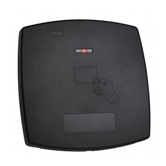
Introduction Introduction The AY-Z12A Long-Range Reader is an RFID proximity card reader, which is utilized with access control systems. The reader can function in one of two scenarios: Single reader installation (default) Multiple reader installation This manual contains the following information: ... -
Page 6: Technical Specifications
Weight 1066 g (2.35 lb) * For maximum range set the reader as a single reader, use Rosslare’s AT-R14 clamshell proximity card, as well as a 16 V power supply and ensure that the installation is as far as possible from any additional electrical devices and not in the proximity to any metal. -
Page 7: Installation
One L-shaped security screw tool Three security screws Installing the AY-Z12A When installing the reader, you must remove the snap-off cover to access the screw holes (Figure 1). Figure 1: Removing the Top Cover The reader must be mounted with the appropriate screws (not supplied), as described in the template provided. -
Page 8: Single Reader Installation
Single Reader Installation The AY-Z12A is designed to function with the best performance when installed isolated from other AY-Z12A readers in a range of at least 2 to 4 meters. The reader is therefore preconfigured as a single installation reader. - Page 9 MP-Z02 spacer. 5. Route the interface cable from the reader to the controller. A linear type power supply is recommended. AY-Z12A Installation Manual...
-
Page 10: Wiring Instructions
Wiring Instructions Wiring Instructions The AY-Z12A is supplied with a 45-cm (18”) pigtail, comprising a 6- conductor cable. To connect the reader to the controller: 1. Prepare the reader cable by cutting its jacket back 4.5 cm (1¼”) and strip the insulation from the wires 1.3 cm (½”). -
Page 11: Configuration Instructions
6. Reconnect the LED Control wire (brown cable) to Ground. The reader’s LED starts flashing continuously and the buzzer sounds. 7. Turn the reader power off. 8. Disconnect the Data 1 wire (white cable) from the Ground. AY-Z12A Installation Manual... - Page 12 Configuration Instructions The reader configuration for multiple reader installation is complete. You can now connect two or three readers within a range of 2–4 meters from one another. AY-Z12A Installation Manual...
-
Page 13: Operation Instructions
LED changes momentarily to green. It then returns to its idle state (red). The range is measured using a Rosslare Proximity Card (P/N AT-11/12) or equivalent. The range also depends on the electrical environment and/or proximity to metal. -
Page 14: Limited Warranty
The full ROSSLARE Limited Warranty Statement is available in the Quick Links section on the ROSSLARE website at www.rosslaresecurity.com. Rosslare considers any use of this product as agreement to the Warranty Terms even if you do not review them. AY-Z12A Installation Manual... - Page 15 United States and Tel: +86 755 8610 6842 Canada Fax: +86 755 8610 6101 support.cn@rosslaresecurity.com Rosslare Security Products, Inc. Southlake, TX, USA India Toll Free: +1-866-632-1101 Rosslare Electronics India Pvt Ltd. Local: +1-817-305-0006 Tel/Fax: +91-20-40147830 Fax: +1-817-305-0069 Mobile: +91-9975768824 support.na@rosslaresecurity.com sales.in@rosslaresecurity.com Europe Rosslare Israel Ltd.


Need help?
Do you have a question about the AY-Z12A and is the answer not in the manual?
Questions and answers