Table of Contents
Advertisement
Quick Links
Installer Guide
Congratulations on your purchase of this product this time.
• To ensure safe and correct use of this product and to gain a thorough understanding of its performance, please read this manual
carefully and retain it for future reference.
• Unauthorized copying or copying of all or part of the contents of this manual is prohibited.
• The specifications of this product and the contents of this manual are subject to change without notice.
• Contact us if you notice any questions, mistakes, or omissions in this product or the contents of this manual.
• We assume no responsibility for any direct or indirect damage caused by the use of this product, whether or not it is faulty.
• We shall not be liable for any direct or indirect damages caused to the product manufactured by this product.
FA02363
Copyright © 2022 DGSHAPE Corporation
R1-220907
https://www.dgshape.com/
Advertisement
Table of Contents

Related Manuals for DGSHAPE DWX-53DC


Summary of Contents for DGSHAPE DWX-53DC
- Page 1 • We assume no responsibility for any direct or indirect damage caused by the use of this product, whether or not it is faulty. • We shall not be liable for any direct or indirect damages caused to the product manufactured by this product. FA02363 Copyright © 2022 DGSHAPE Corporation R1-220907 https://www.dgshape.com/...
-
Page 2: Table Of Contents
Tabl e of Introduction ................................2 ABOUT THE MACHINE ..............................3 Unique features ................................ 3 Pre-installation check ................................. 4 tent Installation and Installation ........................4 Installation location ..............................5 Temperature and humidity ........................6 Installation space ............................7 What's in the Box ................................9 Installation ................................ -
Page 4: Introduction
Introduction ABOUT THE MACHINE ......................3 Unique features ........................3 Pre-installation check ........................4 Installation and Installation ..................4 Installation location ......................5 Temperature and humidity ..................6 Installation space .....................7 What's in the Box .......................... 9 Introducti... -
Page 5: About The Machine
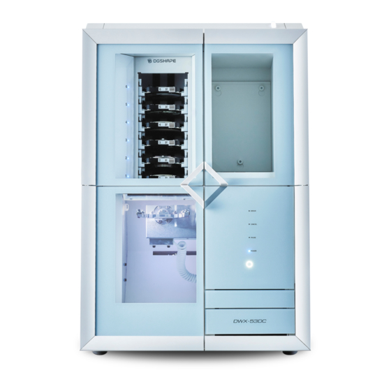
The machine's disc changer automatically manages and switches up to six cutting materials. Continuous machining is possible while using materials in use without waste. Please refer to our site for the latest information on this machine. Relevant • https://www.dgshape.com/ informatio Introducti... -
Page 6: Pre-Installation Check
Pre-installation check Installation and Installation The weight of the main unit alone is 120 kg . Take care when loading/unloading and installing. Note Loading/unloading and installation shall be carried out by at least four persons. Forcible work with a small number of persons may injure your body. If it falls, it may cause injury. Note Hold the projector by the parts shown in the illustration when lifting it. -
Page 7: Installation Location
Pre- installation check Installation location Warning Install the unit in a place that is level, stable, and capable of withstanding the weight of the unit. The total weight of the instrument is more than 120 kg . Failure to do so may result in a serious accident such as a fall, fall or collapse. -
Page 8: Temperature And Humidity
Pre- installation check Temperature and humidity Install the product in a place with specified conditions (temperature, humidity, etc.). Failure to observe this precaution may result in damage to the unit. • Temperature : 5 ~ 40 ℃ • Humidity: 35 to 80% RH (no condensation) Important Use the machine in an environment where the temperature is kept as constant as possible. -
Page 9: Installation Space
Pre- installation check Installation space Allow at least the following space for installation. Installation space Working space 800 mm 900 mm 1,800 mm 1,900 mm Secure sufficient space for the adapter area cover or tool area cover to be opened. 912 mm Relevant •... - Page 10 Pre- installation check Height to be installed Install the product at least 0.6 m from the work floor. This unit is a tabletop-mounted device. Install the product so that it is easily accessible to the power switch and other operating parts during operation.
-
Page 11: What's In The Box
What's in the Box Your digital piano comes with all the items shown below. Check that all parts are included. Air hose (1) Power cord/power plug USB cable (1) Regulator (1) adapter (1 each) Drain hose (1) Open Edge Adapter (1) Automatic correction jig (1) Adapters (6) Adapter for pin material (1) - Page 12 What's in the Box Pre- installation check Cleaning fabric (1) Torque driver*3 Milling bar (4)*2 Cushion Tablet Holder Left (1) Tablet Holder Right (1) Adapter rack (1) (for tablet) (4) Screw (1) Screw (1) Safety Instructions (1) Quick Access Guide (1) Adapter ID label (for option) (1)*4 *1 Attach the adapter ID label (for option) to the adapter base.
-
Page 13: Installation
Installation PREPARATION TO USE THE MACHINE ................12 Check before operation ..................12 Install the aircraft ........................15 Remove the fasteners ..................... 15 Connect the power cord ..................19 Turn on the power ....................21 Retighten the screws of the air nozzle............22 Attach the dust collector .................. -
Page 14: Preparation To Use The Machine
Pre- PREPARATION TO USE THE MACHINE installation check Check before operation Dust collector Since this machine cuts materials, machining scraps are produced during machining. A separate dust collector must be provided. Insert the dust collector hose into the dust collector pipe of the machine and use it. - Page 15 PREPARATION TO USE THE MACHINE Compressor (compressed air supply source) This machine requires compressed air. A compressor must be prepared separately. Warning The pressure of compressed air shall be 1.0 MPa or less. Exceeding this value may cause a serious accident such as an explosion. Warning The compressed air to be supplied shall be free from water, oil, chemicals, and foreign matter.
- Page 16 PREPARATION TO USE THE MACHINE Pre- installation Air hose check Air hose connecting compressor and regulator (1) Prepare an air hose that meets the following conditions. • Hose O.D. ():6 mm (polyurethane resin tube) Important Be sure to use the supplied regulator to supply compressed air. Water receiver The water accumulated in the regulator bowl is discharged little by little, so prepare a water reservoir.
-
Page 17: Install The Aircraft
Install the aircraft Remove the fasteners • To protect the unit from transport vibrations, the unit is fitted with four fasteners. Once the aircraft is installed, remove all fasteners. Turning on the power while the fixture is attached to the aircraft may cause malfunction or failure. •... - Page 18 Install the aircraft Use a Torque Driver to tighten the four mounting screws of Fixture A. Important 0.6 Attach and tighten the N•m red sleeve to the torque screwdriver. Open the adapter area cover. Remove the screws with a torque screwdriver and remove fixture B. Important The torque screwdriver uses a handle and bit.
- Page 19 Install the aircraft Open the tool area cover. Remove the maintenance cover. a. Loosen the screws securing the maintenance cover by hand about two turns. NOTE The screws need not be removed simply by loosening them to make the work more efficient and to prevent the screws from being lost.
- Page 20 Install the aircraft Important The torque screwdriver uses a handle and bit. Do not use sleeves. NOTE To prevent screws from falling into the aircraft, gently press the fixture against the head of the screw with your hand while evenly loosening the screws and remove them together with the fixture. Be sure to remove fixtures C and D and screws.
-
Page 21: Connect The Power Cord
Install the aircraft Connect the power cord Warning Connect to an outlet that conforms to the ratings (voltage, frequency, and current) of the unit. Incorrect voltage or insufficient current can lead to fire or electric shock. Warning Handle power cords, plugs, and outlets correctly and with care. Do not use damaged items. Damaged items may cause fire or electric shock. - Page 22 Install the aircraft Relevant • P. 41 "Connecting Multiple Units" informatio Insta llatio...
-
Page 23: Turn On The Power
Install the aircraft Turn on the power Procedure Close the cover Close all three of the following covers. • Milling area cover • Adapter area cover • Tool area cover Turn on the aircraft's power switch. The aircraft will begin initial operation. The initial operation is complete when the status light changes from blinking to solid. -
Page 24: Retighten The Screws Of The Air Nozzle
Install the aircraft Retighten the screws of the air nozzle. The screws of the air nozzle inside the maintenance cover may loosen due to shaking or vibration when shipped. Retighten the screws after installing the aircraft for safe use of the machine. Necessary items Torque screwdriver... - Page 25 Install the aircraft Tighten the torque driver until it runs idle. Fit the maintenance cover. a. Fit the maintenance cover by passing the screws through the three holes in the maintenance cover. b. Slide the maintenance cover down. c. Tighten the three screws by hand. Close the tool area cover.
-
Page 26: Attach The Dust Collector
Install the aircraft Attach the dust collector This section describes how to install dust collectors with interlocked functions on the machine. If you are using a dust collector that does not have an interlock function, connect the dust collector to the dust collector according to your dust collector's instruction manual. -
Page 27: Install The Regulator
Install the aircraft Install the regulator Warning Do not supply compressed air until the air hose is securely connected. Otherwise, an unexpected accident may occur. Necessary items Screw (for regulator) Air hose Torque screwdriver Regulator (0.6 N・m) 1. Mounting the Regulator on the Aircraft Procedure Temporarily tighten the two screws (for regulator) () on the right side of the aircraft. - Page 28 Install the aircraft Fit the drain hose () to the regulator bowl (). When water accumulates in the bowl, it is drained from the drain hose. Set the water pan. Plug the air hose into the aircraft. Warning Insert the air hose all the way in. Pull lightly to confirm that it is not pulled out. If the plug is loose, it may come off.
- Page 29 Install the aircraft Insert the air hose into the regulator while pushing in the regulator ring. Warning Insert the air hose all the way in. Pull lightly to confirm that it is not pulled out. If the plug is loose, it may come off. Attach the air hose () supplied with your compressor to the left side of the regulator.
- Page 30 Install the aircraft 2. Set the air pressure NOTE When this machine receives CAM data, it automatically changes the intensity of air pressure according to the material to be processed. Procedure Lift up the upper knob (pneumatic adjustment knob) (). Adjust the air pressure a.
-
Page 31: Connect To A Computer
• Destination: 200 Mbyte or more • Error video recording function: 20 GB or more • Because this software is a 32-bit application, it runs on a 64-bit Windows with a WOW64(Windows-On- Windows 64). Relevant • https://www.dgshape.com/ informatio Insta llatio... -
Page 32: Software To Be Installed
Refer to VPanel's user's manual for information on how to read VPanel screens and explain its functions. Dental Driver This is a Windows driver that is required to send data from a computer to this unit. (DWX-53DC screwdriver) Relevant • VPanel for DWX User's Manual informatio Insta... -
Page 33: Install Software
Log on to Windows using the [Computer administrator (or Administrators)] account. Accessing the following URL https://downloadcenter.rolanddg.com/DWX-53DC Download the following software. • [DGSHAPE Dental Driver for Windows]>[Windows Driver [Ver. 1.50]] • [VPanel for DWX]>[setup_VPanel-V4.1.0] Click to download it to the right of the software name. Install the driver. -
Page 34: Connect To A Computer
Connect to a computer Connect to a computer Necessary items USB cable Procedure If the aircraft's power switch is off, turn it on. The aircraft will begin initial operation when the power switch is turned on. The initial operation is complete when the status light changes from blinking to solid. - Page 35 • Machine + Mini PC + Touch Display To [Devices and Printers] when a USB cable is used to connect the machine to the computer on which the driver is installed A DWX-53DC is added and becomes available. Relevant • P. 41 "Connecting Multiple Units"...
- Page 36 Connect to a computer When using the tablet terminal When operating the aircraft using the tablet device, the tablet device can be used by hanging it on the front of the aircraft. You can route the following two cables through the inside of the aircraft. •...
- Page 37 Connect to a computer Fit the tablet holder on the tablet base. Tighten the screws after adjusting the tablet holder. Pass the cable connecting to the tablet terminal through the cable entry on the rear of the aircraft. Pass the cable through the insertion slot so that the terminal to be connected to the tablet terminal is on the tablet base side.
- Page 38 Connect to a computer Connect the cable to the tablet and place it on the tablet holder. Important Do not use USB cable. Do not bend it. If it is folded, the cable may be broken. If you connect USB cable to the bottom of the tablet, placing the tablet on top of the tablet holder will bend the cable.
- Page 39 Connect to a computer Connect the cable terminal on the rear side of the aircraft. Connect USB cable between the aircraft and the tablet device to USB connector on the back of the machine. Connect the charging cable of the tablet device to an electrical outlet. Insta llatio...
- Page 40 Connect to a computer When using a mini PC When using a mini-PC, it can be fixed to VESA mount mounted on the back of this unit. Prepare a VESA mount that conforms to the following VESA standards. • VESA FDMI Standard Part D •...
-
Page 41: Show Vpanel
Connect to a computer Show VPanel VPanel plays an active role as permanent software VPanel is used as a permanent software that operates constantly to manage the machine body and send e-mails. We recommend that you set your VPanel to start automatically when you start up your computer. NOTE VPanel sends an e-mail to inform you when machining is finished or an error occurs. -
Page 42: Exiting Vpanel
Connect to a computer Exiting VPanel Procedure Right-click the (VPanel) icon in the task tray on the desktop, and then click [Finish]. Insta llatio... -
Page 43: Connect Multiple Units
Connect multiple units 2 This setting method is for connecting more than one aircraft of the same model to a single computer. Up to four units can be connected. Before connecting multiple aircraft, distribute the IDs (A to D) that are different from those of the other aircraft one by one and set them accordingly. - Page 44 Connect multiple units The [DWX-53DC Aircraft Sets] window appears. Click [Settings] in [Aircraft ID Settings] on the [General] tab. The [ID Settings-DWX-53DC] window appears. Select an ID that is not used, and then click [OK]. By default, all aircraft IDs are set to [A]. 1 Since the eye is [A], be sure to select one of [B] to [D] for the second and subsequent units.
- Page 45 Connect multiple units Rebooting VPanel. a. Exit VPanel. Right-click the icon in the task tray, and click [Finish]. b. Start VPanel. P. Start up from the [Start] menu (or [Start] window) of 39Windows. The ID you set is now valid. Make sure the aircraft is added to [MACHINE STATUS]. Check that the ID set on the main screen is displayed.
-
Page 46: Switching The Aircraft Operated By Vpanel
Connect multiple units Switching the Aircraft Operated by VPanel Use VPanel to switch the aircraft you want to operate. The aircraft currently selected has a green bar on the left side of the aircraft, as shown below. When switching the aircraft to be operated, click the aircraft image you want to operate in the aircraft list. Relevant •... -
Page 47: Changing The Name And Images Of The Aircraft Displayed On Vpanel
Connect multiple units Changing the Name and Images of the Aircraft Displayed on VPanel By changing the names and airframe printed images displayed on VPanel, you can make it easier to select the device you want to operate. • : Airframe printed image •... - Page 48 Connect multiple units The changed name is displayed on the main screen. Relevant • P. 44 "Switching Aircraft Operated by VPanel " informatio Changing Images of the Aircraft Displayed on VPanel Procedure Displays the main window of VPanel. Right-click the image of the aircraft displayed in [MACHINE STATUS], and then click [Change Image]. Select the image file to be displayed on the [Open] screen.
-
Page 49: Before Starting Work
From the [Apps] window, click the [VPanel for DWX] icon in [VPanel for DWX]. Select the aircraft to be operated. Click the images of DWX-53DC displayed in [Available Aircraft List]. The aircraft whose VPanel is to be operated is displayed at the bottom row. -
Page 50: Running In The Disc Changer
Close all covers. Turn on the power of this unit. Displays VPanel. P. Show 39VPanel Click OK. The [DWX-53DC Aircraft Sets] window appears. Click [Disk Changer Run-in] in the [Maintenance] tab. When the following window appears, click [OK]. Starts running-in. Insta... - Page 51 Before starting work When the completion of work message is displayed, the disc changer completes its running-in operation. Insta llatio...
-
Page 52: Perform Spindle Habituation Operations
Run-in operation is performed to stabilize the rotation of the spindle by spreading grease over the sliding parts inside the spindle. Procedure Close all covers. Displays VPanel. P. Show 39VPanel Click OK. The [DWX-53DC Aircraft Sets] window appears. Click [Spindle Run-in] in the [Maintenance] tab. When the following figure is displayed, click [OK]. Start running-in. Insta llatio... - Page 53 Before starting work When the completion of work message is displayed, the spindle running-in operation is complete. Insta llatio...
-
Page 54: Correcting The Cutting Position Automatically
Before starting work Correcting the cutting position automatically This function compares the value calculated from sensors, etc. with the actual value, and corrects the position of the workpiece zero point, etc. Necessary items Tool for automatic correction Cleaning cloth Detection pin 1. - Page 55 Before starting work Important Clean the back and shaft of the automatic correction tool. Place the detector pin on position 15 of ATC magazine. Insert the detector pin firmly into ATC magazine. Insta llatio...
- Page 56 Before starting work 2. Attaching the automatic correction tool NOTE The automatic correction tool can be attached to any adapter stocker without any problem. Procedure Turn on the power of this unit. The aircraft will begin initial operation. The initial operation is complete when the status light changes from blinking to solid.
- Page 57 Displays VPanel. P. Show 39VPanel Click OK. The [DWX-53DC Aircraft Sets] window appears. Click [Automatic correction] on the [Maintenance] tab. Carry out automatic correction according to the instructions on the screen. After you perform the operations shown on the screen, click [OK] to proceed to the next screen.
- Page 58 Before starting work 4. Remove the detection pin and the automatic correction tool. When the correction value is completed, remove the detection pin and the jig for automatic correction, clean them, and then store them. Procedure Open the tool area cover and adapter area cover. Remove the detection pin.
- Page 59 Before starting work Insta llatio...
-
Page 60: Turn Off
Before starting work Turn off Procedure Turn off the aircraft's power switch. Insta llatio... -
Page 61: Appendix
Appendix Specifications ....................... 60 Expansion terminal ....................60 Coordinate ......................61 Dimensions......................62 List of specifications....................66 System-Requirements for USB Connectivity ............67 endi... -
Page 62: Specifications
Before starting work Spec ifica Expansion terminal tion Important Always power off the aircraft when connecting or disconnecting cables. Connecting or removing the cable while the machine is turned on may cause damage. ※ We are not responsible for the impacts on the equipment connected to this terminal. endi... -
Page 63: Coordinate
cific atio Coordinate A Axis B Axis Origin X Direction Y Direction Z Direction endi... -
Page 64: Dimensions
cific atio Dimensions External Dimensions Front face ER RO CA N PAU S 650 mm 598 mm 321 mm 274 mm 807 mm 831 mm 500 mm 49 mm endi... - Page 65 cific atio Side face 912 mm 560 mm 97 mm 334 mm 763 mm 1,097 mm endi...
- Page 66 cific atio Adaptor dimensions for pin materials 62 mm 22 mm 72 mm endi...
- Page 67 cific atio Detection pin dimensions 33 mm 60 mm Φ4 mm endi...
-
Page 68: List Of Specifications
List of specifications DWX-53DC Ceramics for Dental Cutting Process Resin Processable material *1 Materials for Dental Cutting Process Dental casting wax Dental non-casting cobalt-chromium alloy (before sintering) (zirconia, wax, PMMA, hybrid ridine, PEEK, CoCr synth metal, glass fiber reinforced... -
Page 69: System-Requirements For Usb Connectivity
cific atio System-Requirements for USB Connectivity Computer Windows 11 (64 bit), 10, or 8.1 (32 or 64 bit) preinstalled USB cable Use the supplied USB cabling. When connecting a conversion cable, prepare a USB cable of 3m or less in total including the conversion cable separately. endi... - Page 70 cific atio endi...
Need help?
Do you have a question about the DWX-53DC and is the answer not in the manual?
Questions and answers