
Related Manuals for NARGESA MC650


Summary of Contents for NARGESA MC650
- Page 1 SECTION BENDING MACHINE MC650 NS: 2022-346 INSTRUCTIONS BOOK PRADA NARGESA, S.L Ctra. de Garrigàs a Sant Miquel s/n · 17476 Palau de Santa Eulàlia (Girona) SPAIN Tel. +34 972568085 · nargesa@nargesa.com · www.nargesa.com...
- Page 2 Thank you for choosing our machines www.nargesa.com...
-
Page 3: Table Of Contents
INDEX 1. MACHINE DETAILS ......................3 1.1. Machine identification details ................... 3 1.2. Dimensions ......................3 1.3. Description of the machine ..................3 1.4. Machine part identification ..................4 1.5. General characteristics .................... 5 1.6. Description of the guards ..................6 2. -
Page 4: Machine Details
Picture 1. External dimensions of the MC650 bending machine 1.3. Description of the machine The MC650 bending machine is a machine specifically designed for bending profiles, the majority of which are metal, with different thicknesses and configurations, such as solid profiles, pipes, T-profiles, angles... -
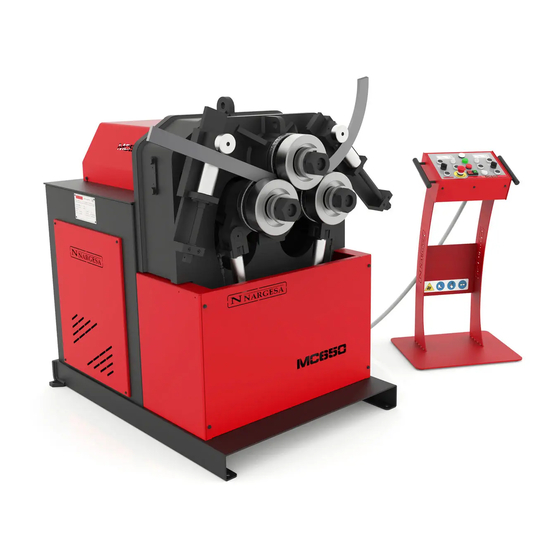
Page 5: Machine Part Identification
SECTION BENDING MACHINE MC650 1.4. Machine part identification Anchor point for horizontal position rotation Bending rollers Upper main roller Straightener roller Lower main rollers Straightener guide nut Hydraulic cylinder Main switch Connector Control panel Back cover Anchoir point Adjustment nut for... -
Page 6: General Characteristics
Figure 2. Nameplate 1.5. General characteristics Motor power 3 Kw / 4 CV to 1400 r.p.m. Intensity 12 / 7 A Voltage supply 230/400 V 3 phased Traction 3 rollers Rollers speed 5 r.p.m. Diameter of rollers 202 mm Diameter of axis Lower 65 mm / Higher 80 mm Useful axis length 160 mm... -
Page 7: Description Of The Guards
SECTION BENDING MACHINE MC650 1.6. Description of the guards The gear motor and all the gears that allow the operation of the machine are located under the main upper cover that protects the mechanisms. Although the major mobile elements are protected by the upper cover, it is necessary to take special precautions during bending operations in order to avoid entrapment between the rollers and the piece being bent. -
Page 8: Transptransport And Storage
2. TRANSPORT AND STORAGE 2.1. Transport There are two ways of carrying out the transportation of the machine: - From the bottom, through the base of the machine, using a pallet jack or forklift as shown in the illustra- tion. Never raise the machine more than 200 mm from the surface in order to prevent the risk of tipping - From the top of the machine, from the anchor point designed for this purpose defined in figure 4, using a crane or forklift. -
Page 9: Maintenance
SECTION BENDING MACHINE MC650 3. MAINTENANCE 3.1. Lubrication of moving parts It is advisable to keep clean the machine moving parts, whenever posible, in order to ensure a correct per- formance and thus make its useful life longer. In order to lubricate the moving parts of the machine that require lubrication, it’s recommended to follow the next instructions: - Clean the surface to be lubricated with a cotton cloth or a soft rag that does not release any threads. -
Page 10: Hydraulic Oil Change
3. We’ll put the roller up and lubricate its axis 4. We repeat three times the operation of moving the roller up and down so the grease can be properly distributed along the surface. Lubrication of the roller axis 5. We clean and lubricate the rear guide and place it in its máximum front point. 6. -
Page 11: Ckeckup Of Hydraulic Instalation
SECTION BENDING MACHINE MC650 - Fill the tank with new hydraulic oil to the level of the sight glass located at the front. The capacity of the tank is approximately 13 litres. - Return the hydraulic assembly to its location and secure it to the machine with the bolts. -
Page 12: Installation And Start Up
4. INSTALLATION AND START UP 4.1. Positioning the machine Locate the machine properly in order to avoid moving it; otherwise, follow the guidelines described in the paragraph transport (no. 2). Must be placed on a flat, level surface to prevent it vibrating and moving during bending operations. -
Page 13: Instructions For Connecting To The Power Supply
IMPORTANT: This machine must be connected to a 400V or 220V source with grounding contact The MC650 is equipped with two 230V / 400V three-phase motors of 3 Kw and 1Kw connected in star or delta in order to connect to a 400V or 220V source. It should be connected to an only power source and to the indicated power source. - Page 14 For voltage 230V Figure 8. Changing the hydraulic engine connections We recommend contacting the Technical Service Department of NARGESA S.L. if you wish to change the operation voltage of the machine in order to be guided and assisted through the procedure.
- Page 15 SECTION BENDING MACHINE MC650 The MC650 bending machine comes equipped with a 230V/ 400V 3Kw three-phase motor for the operation of the rollers and a 230V/ 400V 0.75 Kw three-phase motor to regulate the hydraulic piston, both ready to be connected to a 1 phase 230V power supply. The machine must be connected with the plug installed to a compatible power supply that meets the requirements specified.
-
Page 16: Instructions For Use
5. INSTRUCTIONS FOR USE 5.1. Bending principles The bending of the different profiles and tubes is carried out by passing the material through the three driven rollers located at the front of the machine. Out of these 3 rollers, there is one fixed, and the remaining two are moveable. - Page 17 SECTION BENDING MACHINE MC650 5.3. User guide A control panel with a multi-function touchscreen is used to operate the MC650 hydraulic pipe bender. The machine can also be controlled with a movement button and a four-way joystick for easier roller positioning.
-
Page 18: Instruction Manual
This is largely the man/machine interface. However, reading the steps indicated in the following sections is recommended in order to be able to work with the machine safely and comfortably. 5.3.1. Manual operating mode After turning on the power to the machine (“Power On”), the manual mode graphic interface is displayed on screen. - Page 19 SECTION BENDING MACHINE MC650 The bottom of the screen is reserved for the active mode horizontal menu buttons. In view of the message that appears at the top, the system must be reset in order to work appropriately. To do so, press the button on the horizontal menu.
-
Page 20: Automatic Operating Mode
Besides the hydraulic movement of rollers X and Y which can change the pyramid-like triangle geometry of the machine for different bending radiuses, the MC650 allows synchronized rotation of the three pull rollers for optimal bending on the pieces to be produced. -
Page 21: General Data
SECTION BENDING MACHINE MC650 Automatic operating mode allows you to create and save bending programs for mass production with the possibility of multiple radiuses on each piece. This operating mode is an evolution over the manual opera- ting mode and, as seen below, it is also simple and powerful. - Page 22 Now, you just need to complete the information by pressing on each of the items that appear on screen. They are: 1.- The type of profile (top). 2.- Dimensions and material (middle). 3.- Rollers used and their position on each axis (bottom). 4.- Custom roller (data only visible for custom profiles).
- Page 23 SECTION BENDING MACHINE MC650 Upon pressing the material icon, you’ll see a list from which you can choose the material. Choosing the rollers is just as intuitive. The following graphic will appear upon selecting the top or bottom axis. - 22 -...
-
Page 24: Using The Programs
Using this interface, you can flip each one of the rollers (by pressing the arrow above them) and place them on the axis (by pressing the desired roller). Keep in mind that the order in which you press each one of the rollers will be the order in which they will be inserted on the axis. - Page 25 SECTION BENDING MACHINE MC650 You can save your program with these basic steps but you’ll need to create a new program at some point or load a previously created program. This function can be found by pressing the icon in the horizon- tal menu giving you access to the program management screen.
-
Page 26: Creating A New Program
5.3.4. Creating a New Program All of the programs created are made up of steps. A program can have as many steps as are necessary to generate the geometric shape required based on the piece curving. The first step of a program is known as the “loading step” which is when the position of the bending rollers allows the entrance of the material the machine will work with. - Page 27 You must be aware that any program created with our MC650 bending machine absolutely requires these two steps before bending can begin. The reason is to provide you, as the user, with a comfortable and safe operating mode all while guaranteeing the result obtained for all pieces of the same type of profile or pipe will be excellent for exceptional repeatability throughout the entire series.
- Page 28 Now, with the material secured in the machine, it can be placed in position to begin bending by making the rollers rotate towards the left or right as learned in the section on the manual operating mode. Once the profile or pipe to be processed is in the required position, choose which of the two rollers (X or Y) you want to move to begin making the desired bend.
-
Page 29: Production Mode
SECTION BENDING MACHINE MC650 Remember that a program does not have to create just one bend radius in the piece to be processed. You are the one who decides how many you want to create. And this gives rise to end pieces of varying geome- tric complexity. - Page 30 Therefore, if you wish to make last minute corrections before mass producing pieces when already in pro- duction, you can return to the program editing mode by either pressing the icon on the vertical menu or pressing the automatic mode icon Either way, you will then be able to edit the currently loaded finished program.
- Page 31 SECTION BENDING MACHINE MC650 Use the numerical keyboard to make the adjustment to the height of the chosen axis. To confirm, press the “SET” key. As soon as you finish making the adjustments or corrections in the different steps (if necessary to finish refining the resulting piece), you can return to production mode and begin the series.
-
Page 32: Using Materials And Tools
Now go to step 3 of the program. Push the movement button and the axis for which the height is defined will move into position, creating the beginning of the bend for the piece. Make the bend by getting the ro- llers to rotate left or right, as necessary. - Page 33 SECTION BENDING MACHINE MC650 By using the horizontal menu here on this screen, you can do the following: Create a new material Edit materials Delete materials Switch to the tool management screen (custom rollers) For clarification purposes, remember that each one of the materials is defined by a descriptive name plus a coefficient representing its physical resistance.
- Page 34 This is the custom roller management screen: Just like with the material management screen, the following actions are possible if you press the icons in the horizontal menu: Create a new custom roller Edit an already-existing custom roller Delete a custom roller Switch to the material management screen Remember that each custom roller is defined here with a descriptive name plus an effective diameter.
-
Page 35: Importing And Exporting Data
SECTION BENDING MACHINE MC650 5.3.7. Importing and Exporting Data The same software that runs on the physical machine can be run on a PC with a Windows operating sys- tem. This makes it possible to get the operators and technicians who will intervene in the development and production process familiar with the environment they will later use. -
Page 36: Using The Alarms
All of these data are imported and/or exported using a USB memory stick which can be inserted into the corresponding connector on the control panel. It is also of vital importance to emphasize at this point that you can export and/or import data to the system’s internal memory. This allows you to have a backup copy on the machine itself which can be recovered whenever necessary. - Page 37 SECTION BENDING MACHINE MC650 The question now is how to tell if the system has an activated alarm. You just look to see if the icon appears at the right of the message bar at the top of the screen.
-
Page 38: Working Position
5.4. Working position MC650 can work with the machine bed horizontal or vertical as needed, according to the work to be done. To place the bending machine in horizontal position: 1. Secure the machine at the anchor point indicated in the illustration with a forklift. - Page 39 SECTION BENDING MACHINE MC650 Figure 13. Machine dimensions with the base-plate in a horizontal position WARNING: To change the position of the machine from vertical to horizontal or vice versa, it must be switched off and with the emergency stop button pressed.
-
Page 40: Warnings
6. WARNINGS The MC650 bending machine is designed and assembled to allow the operator to handle the machine and bend the necessary parts in a completely safe manner. Any change to the machine's structure or characteristics could modify the safety offered by the machine, breaching the EC certificate of conformity and could endanger the operator. -
Page 41: Assembly Of The Rollers
SECTION BENDING MACHINE MC650 7. ASSEMBLING OF THE ROLLERS 1. Front nut M30x200 2. Thick washer 3. 65mm roller 4. 65mm roller 5. 40mm roller Figure 14. Nomenclature of the rollers and assembly IMPORTANT NOTE: The clamping nut of the rollers should never be tightened with a wrench and only by hand. If pipe rollers are being used, the nuts must be loose. -
Page 42: Bending Capacity
7.1. Bending capacity MC150B MC200 MC200H MC400 MC650 Min. Min. Min. Min. Min. Measures Measures Measures Measures Measures Profile radius radius radius radius radius 100 x 20 1250 50 x 8 50 x 10 60 x 10 50 x 10... -
Page 43: Optional Accessories
SECTION BENDING MACHINE MC650 8. OPTIONAL ACCESSORIES Set of treated steel rollers Set of 3 sets of treated steel rollers for steel round pipe or stainless steel, thickness bigger than 2 mm. When pipe sizes are smaller, two sizes are included in the same roller. Eg. (25 + 30) Always clean up the rollers well before using stainless steel not to get the pipe contaminated. - Page 44 Set of Sustarín rollers Set of 3 Sustarin rollers for stainless steel pipes, aluminium and delicate materials for thickness smaller than 2.5 mm. When pipe sizes are smaller, two sizes are included in the same roller. Eg. (25 + 30) Susterin rollers do not spoil or contaminate the pipe.
-
Page 45: Technical Annex
Technical annex MC650 Bending Machine General parts diagram Hydraulic group Straightener roller Hydraulic cylinder Electric boxes Electric box· SINGLEPHASE MACHINE Electric box· THREEPHASE MACHINE Electric map· SINGLEPHASE MACHINE Electric map· THREEPHASE MACHINE Electric maps Hydraulic map... - Page 46 SECTION BENDING MACHINE MC650 A1. General parts diagram - A3 -...
- Page 47 - A4 -...
- Page 48 SECTION BENDING MACHINE MC650 - A5 -...
- Page 49 - A6 -...
- Page 50 SECTION BENDING MACHINE MC650 - A7 -...
- Page 51 - A8 -...
- Page 52 SECTION BENDING MACHINE MC650 - A9 -...
- Page 53 - A10 -...
- Page 54 SECTION BENDING MACHINE MC650 - A11 -...
- Page 55 - A12 -...
- Page 56 SECTION BENDING MACHINE MC650 A2. Hydraulic group - 13 -...
- Page 57 - A14 -...
- Page 58 SECTION BENDING MACHINE MC650 - A15 -...
- Page 59 A3. Straightener roller - A16 -...
- Page 60 SECTION BENDING MACHINE MC650 - A17 -...
- Page 61 A4. Hydraulic cylinder - A18 -...
- Page 62 SECTION BENDING MACHINE MC650 - A19 -...
- Page 63 A5. Electric boxes - A20 -...
- Page 64 SECTION BENDING MACHINE MC650 - A21 -...
- Page 65 - A22 -...
- Page 66 SECTION BENDING MACHINE MC650 - A23 -...
- Page 67 - A24 -...
- Page 68 SECTION BENDING MACHINE MC650 A6. Electric box · SINGLEPHASE MACHINE - A25 -...
- Page 69 - A26 -...
- Page 70 SECTION BENDING MACHINE MC650 A7. Electric box· THREEPHASE MACHINE - A27 -...
- Page 71 - A28 -...
- Page 72 SECTION BENDING MACHINE MC650 A8. Electric map· SINGLEPHASE MACHINE - A29 -...
- Page 73 A9. Electric map · THREEPHASE MACHINE - A30 -...
- Page 74 SECTION BENDING MACHINE MC650 A10. Electric maps - A31 -...
- Page 75 - A32 -...
- Page 76 SECTION BENDING MACHINE MC650 - A33 -...
- Page 77 - A34 -...
- Page 78 SECTION BENDING MACHINE MC650 - A35 -...
- Page 79 - A36 -...
- Page 80 SECTION BENDING MACHINE MC650 - A37 -...
- Page 81 A11. Hydraulic map 1. Suction Filter 3/8' 2. 1.5L Hydraulic Pump 3. Electric Motor 0.75Kw 4. Pressure Limiting Valve 5. Solenoid valve 3/2 Spring return 6. Solenoid valve 4/3 Center with circulation 7. Double Piloted non-return Valve 8. Double acting cylinders - A38 -...
- Page 82 OUR RANGE OF MACHINERY IRON WORKERS SECTION BENDING NON-MANDREL HORIZONTAL PRESS MACHINES PIPE BENDER BRAKE TWISTING/SCROLL HYDRAULIC PRESS HYDRAULIC SHEAR BENDING MACHINES BRAKES MACHINES IRON EMBOSSING END WROUGHT IRON GAS FORGES MACHINES MACHINES BROACHING POWER HAMMERS PRESSES FOR LOCKS MACHINES...
Need help?
Do you have a question about the MC650 and is the answer not in the manual?
Questions and answers