
Related Manuals for NARGESA MC650


Summary of Contents for NARGESA MC650
- Page 1 SECTION BENDING MACHINE MC650 INSTRUCTIONS BOOK PRADA NARGESA, S.L Ctra. de Garrigàs a Sant Miquel s/n · 17476 Palau de Santa Eulàlia (GIRONA) SPAIN Tel. +34 972568085 · nargesa@nargesa.com · www.nargesa.com...
- Page 2 Thanks for choosing our machines...
-
Page 3: Table Of Contents
5.4. Working position ……………………………………………………………………………. 6. WARNINGS ……........................6.1. Residual hazards …..................... 6.2. Counter-productive methods ..................6.3. Other recommendations ....................7. ASSEMBLY OF THE ROLLERS ……..................7.1. Bending capacity ......................8. OPTIONAL ACCESSORIES …....................TECHNICAL ANNEX MC650 SECTION BENDING MACHINE INSTRUCTION BOOK... -
Page 4: Machine Details
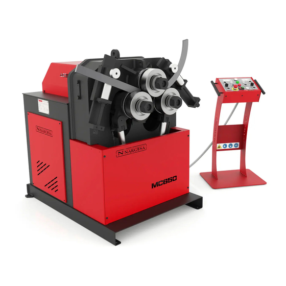
Picture 1. External dimensions of the MC650 bending machine 1.3. Description of the machine The MC650 bending machine is a machine specifically designed for bending profiles, the majority of which are metal, with different thicknesses and configurations, such as solid profiles, pipes, T-profiles, angles... -
Page 5: Machine Part Identification
Connector Control panel Back cover Anchoir point Adjustment nut for of motor for lifting Nuts to secure the position of the straightener roller Anti-rotation plate of the straightener Hydraulic assembly Oil level sight glass MC650 SECTION BENDING MACHINE INSTRUCTION BOOK... -
Page 6: General Characteristics
160 mm Structure material Sheet Weight 1250 Kg Dimensions 1300x990x1300 mm Hydraulic unit features Motor power 0.75 Kw/1 CV a 1400 r.p.m. Intensity 3.5 / 2 A Pump 1,5 l/min Work pressure 200 bars MC650 SECTION BENDING MACHINE INSTRUCTION BOOK... -
Page 7: Description Of The Guards
Although the major mobile elements are protected by the upper cover, it is necessary to take special precautions during bending operations in order to avoid entrapment between the rollers and the piece being bent. Protection drive unit Frontal protection Figure 3. Mechanism protection guards MC650 SECTION BENDING MACHINE INSTRUCTION BOOK... -
Page 8: Transport And Storage
- Temperature of -25 °C to 55 °C or 75 °C for periods not exceeding 24hrs (remember that these temperatures are in storage conditions) - Machines or heavy objects should not be stacked on top MC650 SECTION BENDING MACHINE INSTRUCTION BOOK... -
Page 9: Maintenance
13 litres. - Return the hydraulic assembly to its location and secure it to the machine with the bolts. * We recommend the use of CEPSA HIDRÁULICO HM 68 hydraulic oil. MC650 SECTION BENDING MACHINE INSTRUCTION BOOK... -
Page 10: Installation And Start Up
It is advisable to work under the following atmospheric conditions: - Room temperature between +5 °C and +40 ºC without exceeding an average temperature of +35 °C within 24 hrs. - Humidity between 30% and 90% without water condensation. MC650 SECTION BENDING MACHINE INSTRUCTION BOOK... -
Page 11: Instructions For Connecting To The Power Supply
IMPORTANT: This machine must be connected to an electrical outlet with earthing contact. The MC650 bending machine has a three-phase 230V/400V, 3 Kw motor to move the rollers and a three – phase 230V/400V, 0.75 Kw motor to govern the hydraulic piston, both prepared to connect to a 400V power supply. - Page 12 It is necessary to change the configuration of the plates according to the voltage, as was done with the main motor. Star figure (Default) For voltage 400V Triangle figure For voltage 230V Figure 8. Changing the hydraulic engine connections MC650 SECTION BENDING MACHINE INSTRUCTION BOOK...
- Page 13 Figure 9. Intensity range adjustment We recommend contacting the Technical Service Department of NARGESA S.L. if you wish to change the operation voltage of the machine in order to be guided and assisted through the procedure.
-
Page 14: Instructions For Use
- In the event of not obtaining the proper results, the position of the guide rollers for deformation must be adjusted. - The roller mounting nuts must be tightened by manual force only . 5.2. Assembly of the rollers Figure 10. Position of the rollers in relation to the machine axes MC650 SECTION BENDING MACHINE INSTRUCTION BOOK... -
Page 15: Instruction Manual
5.3. Instruction manual To control the operation of the MC650 hydraulic bending machine, there is a control desk from which the machine can be controlled in a simple and intuitive manner. 1. Emergency stop 2. Of/On 3. Reset 4. Right roller position controllers 5. -
Page 16: Pilot Lights
Once the dangerous situation has been dealt with, it is necessary to unlock the emergency stop button and then reset the machine to continue working with it. MC650 SECTION BENDING MACHINE INSTRUCTION BOOK... -
Page 17: Roller Position Controllers
On the front of the control panel, in addition to the aforementioned controls, you can also find two buttons to control the direction of rotation of the rollers. To do this, just press and maintain pressed the button corresponding to the desired direction, left or right. MC650 SECTION BENDING MACHINE INSTRUCTION BOOK... -
Page 18: Working Position
5.4. Working position MC650 can work with the machine bed horizontal or vertical as needed, according to the work to be done. To place the bending machine in horizontal position: 1. Secure the machine at the anchor point indicated in the illustration with a forklift. - Page 19 To change the position of the machine from vertical to horizontal or vice versa, it must be switched off and with the emergency stop button pressed. When carrying out the operation, make sure the control panel and power cables are not caught. MC650 SECTION BENDING MACHINE INSTRUCTION BOOK...
-
Page 20: Warnings
6. WARNINGS The MC650 bending machine is designed and assembled to allow the operator to handle the machine and bend the necessary parts in a completely safe manner. Any change to the machine's structure or characteristics could modify the safety offered by the machine, breaching the EC certificate of conformity and could endanger the operator. -
Page 21: Assembly Of The Rollers
Figure 13. Nomenclature of the rollers and assembly IMPORTANT NOTE: The clamping nut of the rollers should never be tightened with a wrench and only by hand. If pipe rollers are being used, the nuts must be loose. MC650 SECTION BENDING MACHINE INSTRUCTION BOOK... -
Page 22: Bending Capacity
50,8 x 3 63,5 x 3 63,5 x 3 76,2 x 2 101,6 x 3 = 2” x 3 = 2”1/2 x 3 =2”1/2 x 3 = 3” x 2 = 4” x 3 Optional rollers MC650 SECTION BENDING MACHINE INSTRUCTION BOOK... -
Page 23: Optional Accessories
In order to facilitate the bending of certain more delicate materials that require a very good surface finish or to facilitate the bending of more common sections, NARGESA has designed a series of rollers that can be purchased at an official dealership or by directly by contacting NARGESA S.L. - Page 24 When pipe sizes are smaller, two sizes are included in the same roller. Eg. (25+30) or (1/2"+1"1/4) Susterin rollers do not spoil or contaminate the pipe. For any other size or profile please ask the manufacturer. MC650 SECTION BENDING MACHINE INSTRUCTION BOOK...
-
Page 25: Technical Annex
Technical annex MC650 Bending Machine General parts diagram Hydraulic group Straightener roller Hydraulic cylinder Electrical box Electric maps Hydraulic map MC650 SECTION BENDING MACHINE INSTRUCTION BOOK... - Page 26 A1. General parts diagram MC650 SECTION BENDING MACHINE INSTRUCTION BOOK...
- Page 27 MC650 SECTION BENDING MACHINE INSTRUCTION BOOK...
- Page 28 MC650 SECTION BENDING MACHINE INSTRUCTION BOOK...
- Page 29 MC650 SECTION BENDING MACHINE INSTRUCTION BOOK...
- Page 30 MC650 SECTION BENDING MACHINE INSTRUCTION BOOK...
- Page 31 MC650 SECTION BENDING MACHINE INSTRUCTION BOOK...
- Page 32 MC650 SECTION BENDING MACHINE INSTRUCTION BOOK...
- Page 33 A2. Hydraulic group MC650 SECTION BENDING MACHINE INSTRUCTION BOOK...
- Page 34 MC650 SECTION BENDING MACHINE INSTRUCTION BOOK A 10...
- Page 35 MC650 SECTION BENDING MACHINE INSTRUCTION BOOK A 11...
- Page 36 A3. Straightener roller MC650 SECTION BENDING MACHINE INSTRUCTION BOOK A 12...
- Page 37 MC650 SECTION BENDING MACHINE INSTRUCTION BOOK A 13...
- Page 38 A4. Hydraulic cylinder MC650 SECTION BENDING MACHINE INSTRUCTION BOOK A 14...
- Page 39 MC650 SECTION BENDING MACHINE INSTRUCTION BOOK A 15...
- Page 40 A5. Electrical box MC650 SECTION BENDING MACHINE INSTRUCTION BOOK A 16...
- Page 41 MC650 SECTION BENDING MACHINE INSTRUCTION BOOK A 17...
- Page 42 MC650 SECTION BENDING MACHINE INSTRUCTION BOOK A 18...
- Page 43 A6. Electric maps Roller motor Pump motor MC650 SECTION BENDING MACHINE INSTRUCTION BOOK A 19...
- Page 44 MC650 SECTION BENDING MACHINE INSTRUCTION BOOK A 20...
- Page 45 MC650 SECTION BENDING MACHINE INSTRUCTION BOOK A 21...
- Page 46 A7. Hydraulic map 1. Filter 2. Hydraulic pump 3. Electric motor 4. Pressure limiter 5. Bending solenoid 6. Cylinder solenoid 7. Piloted non-return valves 8. Roller position cylinders MC650 SECTION BENDING MACHINE INSTRUCTION BOOK A 22...
- Page 47 3. Complete the form with your details and press Send 4. The window Message Sent confirms your data has been successfully sent to Prada Nargesa SL. Your machine has been registered and has a warranty of three years in total.
Need help?
Do you have a question about the MC650 and is the answer not in the manual?
Questions and answers