
Related Manuals for NARGESA MC650


Summary of Contents for NARGESA MC650
- Page 1 SECTION BENDING MACHINE MC650 NS: 2020-240 INSTRUCTIONS BOOK PRADA NARGESA, S.L Ctra. de Garrigàs a Sant Miquel s/n · 17476 Palau de Santa Eulàlia (Girona) SPAIN Tel. +34 972568085 · nargesa@nargesa.com · www.nargesa.com...
- Page 2 Thank you for choosing our machines www.nargesa.com...
-
Page 3: Table Of Contents
INDEX 1. MACHINE DETAILS ......................... 3 1.1. Machine identification details ..................3 1.2. Dimensions ........................3 1.3. Description of the machine ..................3 1.4. Machine part identification ..................4 1.5. General characteristics ....................5 1.6. Description of the guards ..................... 6 2. -
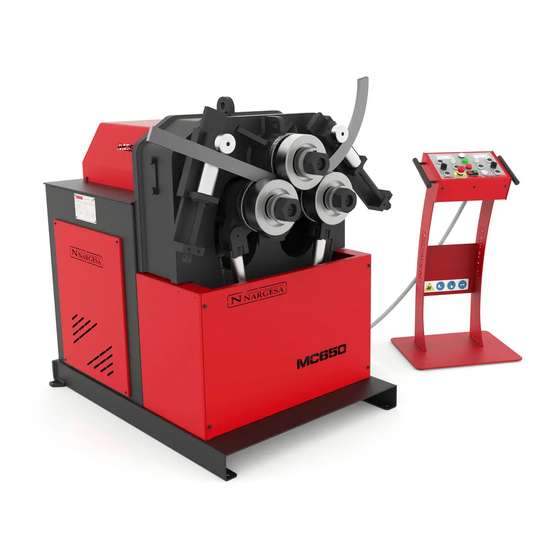
Page 4: Machine Details
Picture 1. External dimensions of the MC650 bending machine 1.3. Description of the machine The MC650 bending machine is a machine specifically designed for bending profiles, the majority of which are metal, with different thicknesses and configurations, such as solid profiles, pipes, T-profiles, angles... -
Page 5: Machine Part Identification
SECTION BENDING MACHINE MC650 1.4. Machine part identification Anchor point for horizontal position rotation Bending rollers Upper main roller Straightener roller Lower main rollers Straightener guide nut Hydraulic cylinder Main switch Connector Control panel Back cover Anchoir point Adjustment nut for... -
Page 6: General Characteristics
Figure 2. Nameplate 1.5. General characteristics Motor power 3 Kw / 4 CV to 1400 r.p.m. Intensity 12 / 7 A Voltage supply 230/400 V 3 phased Traction 3 rollers Rollers speed 5 r.p.m. Diameter of rollers 202 mm Diameter of axis Lower 65 mm / Higher 80 mm Useful axis length 160 mm... -
Page 7: Description Of The Guards
SECTION BENDING MACHINE MC650 1.6. Description of the guards The gear motor and all the gears that allow the operation of the machine are located under the main upper cover that protects the mechanisms. Although the major mobile elements are protected by the upper cover, it is necessary to take special precautions during bending operations in order to avoid entrapment between the rollers and the piece being bent. -
Page 8: Transptransport And Storage
2. TRANSPORT AND STORAGE 2.1. Transport There are two ways of carrying out the transportation of the machine: - From the bottom, through the base of the machine, using a pallet jack or forklift as shown in the illustra- tion. Never raise the machine more than 200 mm from the surface in order to prevent the risk of tipping - From the top of the machine, from the anchor point designed for this purpose defined in figure 4, using a crane or forklift. -
Page 9: Maintenance
SECTION BENDING MACHINE MC650 3. MAINTENANCE 3.1. Lubrication of moving parts It is advisable to keep clean the machine moving parts, whenever posible, in order to ensure a correct per- formance and thus make its useful life longer. In order to lubricate the moving parts of the machine that require lubrication, it’s recommended to follow the next instructions: - Clean the surface to be lubricated with a cotton cloth or a soft rag that does not release any threads. -
Page 10: Hydraulic Oil Change
3. We’ll put the roller up and lubricate its axis 4. We repeat three times the operation of moving the roller up and down so the grease can be properly distributed along the surface. Lubrication of the roller axis 5. We clean and lubricate the rear guide and place it in its máximum front point. 6. -
Page 11: Ckeckup Of Hydraulic Instalation
SECTION BENDING MACHINE MC650 - Fill the tank with new hydraulic oil to the level of the sight glass located at the front. The capacity of the tank is approximately 13 litres. - Return the hydraulic assembly to its location and secure it to the machine with the bolts. -
Page 12: Installation And Start Up
4. INSTALLATION AND START UP 4.1. Positioning the machine Locate the machine properly in order to avoid moving it; otherwise, follow the guidelines described in the paragraph transport (no. 2). Must be placed on a flat, level surface to prevent it vibrating and moving during bending operations. -
Page 13: Instructions For Connecting To The Power Supply
IMPORTANT: This machine must be connected to an electrical outlet with earthing contact. The MC650 bending machine has a three-phase 230V/400V, 3 Kw motor to move the rollers and a three – phase 230V/400V, 0.75 Kw motor to govern the hydraulic piston, both prepared to connect to a 400V power supply. - Page 14 Changing the hydraulic motor connection: The motor of the hydraulic system is located inside the cabinet, at the bottom of the machine. The hydraulic assembly is inside the cabinet. The motor is secured to the tank and on its front is the connection box.
- Page 15 Figure 9. Intensity range adjustment We recommend contacting the Technical Service Department of NARGESA S.L. if you wish to change the operation voltage of the machine in order to be guided and assisted through the procedure.
- Page 16 The MC650 bending machine comes equipped with a 230V/ 400V 3Kw three-phase motor for the operation of the rollers and a 230V/ 400V 0.75 Kw three-phase motor to regulate the hydraulic piston, both ready to be connected to a 1 phase 230V power supply. The machine must be connected with the plug installed to a compatible power supply that meets the requirements specified.
-
Page 17: Instructions For Use
SECTION BENDING MACHINE MC650 5. INSTRUCTIONS FOR USE 5.1. Bending principles - The motor of the bending machine is controlled from the control panel. - The radius of the curve is controlled by acting on the push buttons on the control panel, adjusting the height of the two lower rollers. -
Page 18: Instruction Manual
5.3. Instruction manual To control the operation of the MC650 hydraulic bending machine, there is a control desk from which the machine can be controlled in a simple and intuitive manner. 1. Emergency stop 2. Of/On 3. Reset 4. Right roller position controllers 5. -
Page 19: Pilot Lights
SECTION BENDING MACHINE MC650 Nevertheless, to know the function of each of the elements of the control desk, it is recommended to read the following sections: 5.3.1. Pilot lights The control panel has three pilot lights, the function of each of which is explained below. -
Page 20: Roller Position Controllers
5.3.3. Roller position controllers To control each of the pistons producing upward and downward movement of the left and right hand rollers, the control desk has two different areas, one at each side of the front of the control desk. Obviously, as they carry out identical functions regarding the control of each of the pistons, we will explain the operation generically, without specifying which piston is being referred to, to make it more comprehensible. -
Page 21: Working Position
SECTION BENDING MACHINE MC650 5.4. Working position MC650 can work with the machine bed horizontal or vertical as needed, according to the work to be done. To place the bending machine in horizontal position: 1. Secure the machine at the anchor point indicated in the illustration with a forklift. - Page 22 Figure 13. Machine dimensions with the base-plate in a horizontal position WARNING: To change the position of the machine from vertical to horizontal or vice versa, it must be switched off and with the emergency stop button pressed. When carrying out the operation, make sure the control panel and power cables are not caught. - 21 -...
-
Page 23: Warnings
SECTION BENDING MACHINE MC650 6. WARNINGS The MC650 bending machine is designed and assembled to allow the operator to handle the machine and bend the necessary parts in a completely safe manner. Any change to the machine's structure or characteristics could modify the safety offered by the machine, breaching the EC certificate of conformity and could endanger the operator. -
Page 24: Assembly Of The Rollers
7. ASSEMBLING OF THE ROLLERS 1. Front nut M30x200 2. Thick washer 3. 65mm roller 4. 65mm roller 5. 40mm roller Figure 14. Nomenclature of the rollers and assembly IMPORTANT NOTE: The clamping nut of the rollers should never be tightened with a wrench and only by hand. If pipe rollers are being used, the nuts must be loose. -
Page 25: Bending Capacity
SECTION BENDING MACHINE MC650 7.1. Bending capacity MC150B MC200 MC200H MC400 MC650 Min. Min. Min. Min. Min. Measures Measures Measures Measures Measures Profile radius radius radius radius radius 100 x 20 1250 50 x 8 50 x 10 60 x 10... -
Page 26: Optional Accessories
8. OPTIONAL ACCESSORIES Set of treated steel rollers Set of 3 sets of treated steel rollers for steel round pipe or stainless steel, thickness bigger than 2 mm. When pipe sizes are smaller, two sizes are included in the same roller. Eg. (25 + 30) Always clean up the rollers well before using stainless steel not to get the pipe contaminated. - Page 27 SECTION BENDING MACHINE MC650 Set of Sustarín rollers Set of 3 Sustarin rollers for stainless steel pipes, aluminium and delicate materials for thickness smaller than 2.5 mm. When pipe sizes are smaller, two sizes are included in the same roller. Eg. (25 + 30) Susterin rollers do not spoil or contaminate the pipe.
-
Page 28: Technical Annex
Technical annex MC650 Bending Machine General parts diagram Hydraulic group Straightener roller Hydraulic cylinder Electric box· THREEPHASE MACHINE Electric maps· THREEPHASE MACHINE Electric box· SINGLEPHASE MACHINE Electric maps· SINGLEPHASE MACHINE Hydraulic map... - Page 29 SECTION BENDING MACHINE MC650 A1. General parts diagram - A3 -...
- Page 30 - A4 -...
- Page 31 SECTION BENDING MACHINE MC650 - A5 -...
- Page 32 - A6 -...
- Page 33 SECTION BENDING MACHINE MC650 - A7 -...
- Page 34 - A8 -...
- Page 35 SECTION BENDING MACHINE MC650 - A9 -...
- Page 36 A2. Hydraulic group - A10 -...
- Page 37 SECTION BENDING MACHINE MC650 - A11 -...
- Page 38 - A12 -...
- Page 39 SECTION BENDING MACHINE MC650 A3. Straightener roller - A13 -...
- Page 40 - A14 -...
- Page 41 SECTION BENDING MACHINE MC650 A4. Hydraulic cylinder - A15 -...
- Page 42 - A16 -...
- Page 43 SECTION BENDING MACHINE MC650 A5. Electric box· THREEPHASE MACHINE - A17 -...
- Page 44 - A18 -...
- Page 45 SECTION BENDING MACHINE MC650 A6. Electric mapS · THREEPHASE MACHINE - A19 -...
- Page 46 - A20 -...
- Page 47 SECTION BENDING MACHINE MC650 - A21 -...
- Page 48 A7. Electric box · SINGLEPHASE MACHINE - A22 -...
- Page 49 SECTION BENDING MACHINE MC650 - A23 -...
- Page 50 A8. Electric maps· SINGLEPHASE MACHINE - A24 -...
- Page 51 SECTION BENDING MACHINE MC650 - A25 -...
- Page 52 - A26 -...
- Page 53 SECTION BENDING MACHINE MC650 A9. Hydraulic map 1. Filter 2. Hydraulic pump 3. Electric motor 4. Pressure limiter 5. Bending solenoid 6. Cylinder solenoid 7. Piloted non-return valves 8. Roller position cylinders - A27 -...
- Page 54 OUR RANGE OF MACHINERY IRON WORKERS SECTION BENDING NON-MANDREL HORIZONTAL PRESS MACHINES PIPE BENDER BRAKE TWISTING/SCROLL HYDRAULIC PRESS HYDRAULIC SHEAR BENDING MACHINES BRAKES MACHINES IRON EMBOSSING END WROUGHT IRON GAS FORGES MACHINES MACHINES BROACHING POWER HAMMERS PRESSES FOR LOCKS MACHINES...
Need help?
Do you have a question about the MC650 and is the answer not in the manual?
Questions and answers