Table of Contents
Advertisement
Quick Links
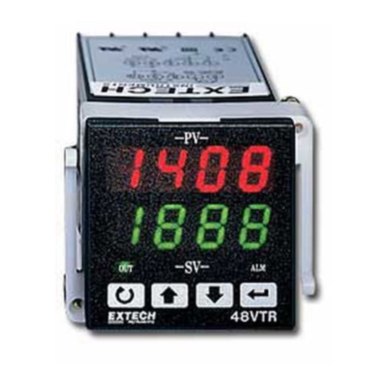
Model 48VTR 1/16 DIN Process Controller
1. INTRODUCTION
The 48VTR is a microprocessor-based device which can compare a process input
(thermocouple, RTD, or analog input) to a user-programmable setpoint and adjust the
process (via relay or analog output), to bring the process to the desired setpoint. This Three-
Mode PID controller offers:
Simultaneous Process Value (PV) and Setpoint Value (SV) display
Automatic alarm functions (11 in all)
Auto-Tuning automatically tailors the controller's response to a specific process
Security lock-out
Ramp-to-Setpoint and Soak functions
Input selectability
Instruction Manual
English / Español
Advertisement
Table of Contents

Subscribe to Our Youtube Channel
Related Manuals for Extech Instruments 48VTRR3


Summary of Contents for Extech Instruments 48VTRR3
- Page 1 Instruction Manual English / Español Model 48VTR 1/16 DIN Process Controller 1. INTRODUCTION The 48VTR is a microprocessor-based device which can compare a process input (thermocouple, RTD, or analog input) to a user-programmable setpoint and adjust the process (via relay or analog output), to bring the process to the desired setpoint. This Three- Mode PID controller offers: Simultaneous Process Value (PV) and Setpoint Value (SV) display Automatic alarm functions (11 in all)
-
Page 2: Specifications
2. SPECIFICATIONS 2.1 General Specifications Display Dual 7-segment 4-digit LED Displays: Red (PV), Green (SV) Status Indicators For Control output, Alarm output, Over range, Auto- Tune, and Open Input LED display span -1999 to 9999 counts max (Programmable) Indicating Accuracy +0.2% Full Scale +1 digit Sampling Time 1 reading per 0.25 seconds... -
Page 3: Mounting And Wiring
2.3 Output Specifications Control Output Relay 5 Amps @ 110V AC; SPDT (Resistive Load) Control Output DC Voltage (Pulsed) 24V DC (DC drive for SSR) ON: 24V DC typical, 29V DC max. OFF: 0.3V DC max Analog Control Output (Current) 4-20mA DC;... -
Page 4: Meter Description
Warning: An independent redundant alarm should be used if control/alarm relay failure could result in potential harm or damage. Control Output 2-wire RTD 4-wire RTD 4-20 Short terminals 1 and 2 Leave the 4th wire open Analog Alarm Output Figure 3 4. -
Page 5: Return Key
5.3 Status Indicators 'ALM' Status Indicator (Alarm Relay Status LED) This LED is lit in red when the Alarm relay is active. Also, this LED flashes when the Alarm is configured as an Event/Soak timer and is in the process of counting down. - Page 6 Table I - Programming Level Parameters (default values) at a glance 1st Prog. Level 2nd Prog. Level 3rd Prog. Level 4th Prog. Level RAmp (0.0) Pb (0) REmo (0) LoCA (0.0) oPoF (0.0) Ti (240) P-L (4) HiCA 1000 A1SP or timE Td (40) A1FU (2) TunE (1)
- Page 7 Proportional band value. Setting range from 0.0 to 100.0% of controller's Span. Default = 10.0. Set Pb to 0.0% for ON/OFF control action. This value is automatically calculated by activating the AUTO TUNE function. If desired, the user can later adjust this parameter to better suit the application. Integral (Reset) value.
- Page 8 Decimal Point selection. no decimal point 0.1 resolution 0.01 resolution (cannot use this setting for temperature inputs) 0.001 resolution (cannot use this setting for temperature inputs) Control Output Cycle Time. Range: 0 to 100 seconds. This is the period of time the controller waits between output percentage changes.
-
Page 9: Auto Tuning
9. FOURTH PROGRAMMING LEVEL PARAMETERS Press and hold the SCROLL and RETURN keys simultaneously for 5 seconds to enter this level from the third programming level. To return to normal operation at any time, press the RETURN key. LoCA and HiCA: Low and High Input Calibration values. Refer to Section 10 “Calibration”... - Page 10 Table III - Programmable Auto Tune Initialization Modes Auto Tune ‘Initialization Modes’ Auto Tune can only be initiated manually with the SV not equal to the PV Auto Tune can only be initiated manually with the PV equal to the SV. Auto Tunes automatically when the controller is FIRST powered up if the PV <...
- Page 11 13. RAMP AND SOAK FUNCTIONS The Extech 48VTR controller operates as a fixed setpoint controller. However, the controller offers several advanced features which can enhance your application. These include Ramp-to-Setpoint and Soak/Event Timers. Refer to the details below. 13.1 Ramp-to-Setpoint (‘rAmP’ Parameter) To limit the rate at which the controller allows the process (PV) to move towards setpoint (SV), enter a value in units per minute for the 'rAmP' parameter.
-
Page 12: Customer Service
15. WARRANTY EXTECH INSTRUMENTS CORPORATION warrants this instrument to be free of defects in parts and workmanship for one year from date of shipment (a limited warranty may apply on sensors and cables). If it should become necessary to return the instrument for service during or beyond the warranty period, contact the Customer Service Department at (781) 890-7440 ext. -
Page 13: Appendix B - Programming Example
'06' Process High Alarm with Standby Sequence: Same as the Process High Alarm but no relay action takes place until the process PV reaches the setpoint for a second time. Also known as "Startup Inhibit" and is useful for avoiding alarm trips during startup. - Page 14 Programming Level 1 A1SP (Alarm Setpoint): Set to 600 F. Temperature at which the alarm will switch on the annunciator. Tuning the Controller (Level 2 parameters) The best plan of attack with tuning is running the Auto Tune utility. Auto Tune will automatically program the controller to respond with little process oscillation around setpoint and minimal overshoot on oven heat-up.
Need help?
Do you have a question about the 48VTRR3 and is the answer not in the manual?
Questions and answers