
Related Manuals for Extech Instruments 96VFL Series


Summary of Contents for Extech Instruments 96VFL Series
- Page 1 USER MANUAL Process PID Controllers Model 96VFL DIN Controller Model 48VFL DIN Controller...
-
Page 2: Table Of Contents
Contents Introduction ....................4 Safety ......................5 Panel Cut-out, Dimensions, and Mounting ............6 48VFL Mounting ......................... 6 96VFL Mounting ......................... 6 Wiring ......................7 IMPORTANT SAFETY WIRING CONSIDERATIONS ..............7 AC Power Wiring ........................ 7 Thermocouple Input ......................7 Analog Input (4-20mA) optional ................... - Page 3 11.1 Input Type Selection ......................27 11.2 Low and High Limit Considerations ..................27 11.3 Alarm Function and Alarm Modes Lists ................28 11.4 ON-OFF Alarm Timers ....................... 29 11.5 RS-485 Interface Option ....................30 12. Programming Menu 5 (Linear Input) ............. 30 13.
-
Page 4: Introduction
1. Introduction Thank you for selecting the Extech VFL Process Controller. The VFL series uses intelligent algorithms (including fuzzy logic) to offer highly precise process control. The wide array of features and functions are easily configured in the four program menu levels. Controller Wiring The controller must be wired before use. -
Page 5: Safety
2. Safety The installation, wiring, and maintenance of this process controller must be performed by qualified electrical technicians. Please read the entire user manual, including all safety information, before using this device. No user serviceable parts. WARNINGS • The electrical power required by this controller is hazardous. Use care when connecting the controller to power and other devices. -
Page 6: Panel Cut-Out, Dimensions, And Mounting
3. Panel Cut-out, Dimensions, and Mounting FIGURE 3.1: VFL CUT-OUT AND DIMENSIONS 48VFL 96VFL Units: mm (columns ‘a’ and ‘b’ are +/- 0.5mm) 3.1 48VFL Mounting 1. Remove the plastic mounting bracket and slide the controller into the panel, through the cutout. -
Page 7: Wiring
4. Wiring FIGURE 4.1: SERIES VFL WIRING (48VFL ON LEFT, 96VFL ON RIGHT) 4.1 IMPORTANT SAFETY WIRING CONSIDERATIONS • Before wiring, verify the installed hardware options: Input (TC, RTD, Analog); Output (relay, analog, dc trigger). The controller label should match the model number ordered, contact Extech if there is any uncertainty. -
Page 8: Rtd Input (2, 3, Or 4 Wire)
4.5 RTD Input (2, 3, or 4 wire) 48/96 VTR: 3-wire RTDs are most common and are wired to 8, 9, and 10 on the 96VFL and terminals 7, 8, and 9 on the 48VFL as shown in the diagrams above. 96VFL: For 2-wire RTD, connect across terminals 8 and 9 and jump 9 to 10. -
Page 9: Analog Output Wiring
4.8 Analog Output Wiring Analog outputs are optional. Analog outputs are available across the same terminals that are used for the relay outputs. See Control Relay terminals table above. Parameter ‘Ct’ (PID Menu 3) must be set to ‘0’ when using an analog output. 4.9 Alarm Relay Output One relay is supplied in a standard VFL controller, the second alarm is optional. -
Page 10: Product Description
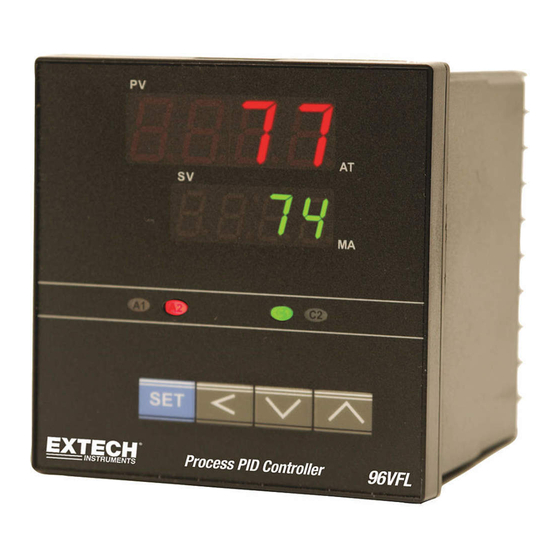
5. Product Description The numbered call-out items below describe the basic operational functions for the displays, indicators, and keys. Advanced uses are explained in the Keypad Descriptions and Display Descriptions sections, and throughout this manual. 5.1 96VFL Front Panel FIGURE 5.1: 96VFL FRONT PANEL 1. -
Page 11: 48Vfl Front Panel
5.2 48VFL Front Panel FIGURE 5.2: 48VFL FRONT PANEL 1. Process Variable (PV) display digits (red) show the process input. 2. Setting Variable (SV) display digits (green) show the programmed setpoint. 3. Alarm 1 (A1) and Alarm 2 (A2) relay status indicators. 4. -
Page 12: Display Descriptions
• Use the up/down arrows to change a setting in the programming menus. In most cases, the SHIFT key is used to select a digit for editing, and then the up/down arrows are used to change the digit value. SET is then used to confirm and continue scrolling. Combination Keystrokes •... - Page 13 Status Indicators ‘A1’ and ‘A2’ Relay Status LEDs These LEDs light when the associated Alarm relay is active. It flashes when the Alarm is configured as an ON or OFF Timer and the timer is running. Refer to the Alarm Timers section.
-
Page 14: Process Control
6. Process Control 6.1 Connect the Inputs The input types (thermocouple, RTD, analog) are hardware dependent. The part number ordered, and the product label indicate the input type. If you are uncertain, please contact Extech. Wire the input as described in the Wiring section. 6.2 Connect the Outputs The output types (relay, dc trigger, analog) are hardware dependent. -
Page 15: Analog Output Option
Caution: With DC Trigger installed in your controller do not wire an external AC or DC voltage signal to the DC Trigger terminals. 6.7 Analog Output Option With the analog output option, the controller supplies 4-20mA to the process. Up to two 4-20 outputs can be installed (see the Wiring section for rear-terminal designations). -
Page 16: Pid 'Time Proportioning' Control
Proportional-only control adjusts the controller output, proportional to the proximity of PV to SV. The closer to setpoint, the lower the output %. The further from setpoint, the higher the output %. Proportional-only control, however, has a side effect (known as droop or offset) where the process is brought to equilibrium, but not exactly at setpoint. -
Page 17: Proportional Control Considerations
FIGURE 6.2: TIME PROPORTIONING CONTROL EXAMPLES FIGURE 6.2a FIGURE 6.2b FIGURE 6.2c Figure 6.2a: The controller is calling for 80% power since the PV is far from the SV. Figure 6.2b: The PV is closer to SV, so the controller calls for 50% power. Figure 6.2c: The PV is very close to SV, so the output is at 10% power. - Page 18 FIGURE 6.3: PROPORTIONAL BAND EXAMPLES Pb setting too narrow When Proportional Band is set too narrow, the PV rises too quickly and typically overshoots the SV, as shown. Pb setting too wide When Proportional Band is set too wide, the PV rises too slowly and may never reach the SV.
-
Page 19: Dead-Band Considerations
6.12 Dead-Band Considerations The dead band (db) parameter (Menu 3, PID) allows you to control whether the primary output and the secondary cooling output can be ON at the same time. Set ‘db’ to a positive value to restrict the outputs from being ON at the same time. Set ‘db’ to a negative value to allow the outputs to be ON at the same time. -
Page 20: Programming Menu Basics
7. Programming Menu Basics The VFL series controllers have 5 programming levels. 1. MENU 1 (User): Set control/alarm setpoints, auto tune, and manual control. 2. MENU 2 (Soft-start): Set soft-start and ramp-to-setpoint limits. 3. MENU 3 PID Tuning level: Set tuning parameters, parameter lock, hysteresis, and more. 4. - Page 21 Programming Menu Level Overview Menu 1 (SP) Menu 2 (Soft) Menu 3 (PID) Menu (Option) Menu 5 (Linear) USER LEVEL SOFT START LEVEL PID LEVEL OPTION LEVEL LINEAR INPUT USER Menu Notes: When the secondary output (cooling) is not selected, CPb, Cti, Ctd, HYS2, and db parameters do not appear in the menu.
-
Page 22: Programming Menu 1 (User Level)
8. Programming Menu 1 (User level) • Press the SET key to access Menu 1 (User level). • Continue to use the SET key to scroll through the menu. At the end of the menu you will return to the normal operating screen. This applies to Menu level 1 only. •... -
Page 23: Programming Menu 2 (Soft Start Level)
9. Programming Menu 2 (Soft Start level) • From any display, long press the SET and SHIFT (<) keys for five (5) seconds to enter the Menu 2-3-4 ‘Level’ selection screen. Use the up/down arrows to select Menu 2 (or Menu 3 or 4). -
Page 24: Programming Menu 3 (Pid)
10. Programming Menu 3 (PID) • From any display, long press the SET and SHIFT (<) keys for five (5) seconds to enter the Menu 2-3-4 ‘Level’ selection screen. Use the up/down arrows to select Menu 3 (or Menu 2 or 4). •... - Page 25 Hysteresis Alarm 1 Region where relay switching is 0 ~ 2000 disabled. Region extends equally above and below A1SP (Menu 1). Same as ‘A1HY’ for Alarm 2. 0 ~ 2000 Hysteresis Alarm 2 Set to a negative value to allow -1000 ~ 1000 Dead band OUT 1 and OUT 2 to be ON at the...
-
Page 26: Programming Menu 4 (Option)
11. Programming Menu 4 (Option) • From any display, long press the SET and SHIFT (<) keys for five (5) seconds to enter the Menu 2-3-4 ‘Level’ selection screen. Use the up/down arrows to select Menu 4 (or Menu 2 or 3). •... -
Page 27: Input Type Selection
Alarm 2 Same as ‘A1FU’ for Alarm 2. See Alarm Differential function section low alarm function Alarm 2 mode Select a specialty mode from the See Alarm mode None Alarm mode list (Section 11.3). section Set a controller address for 00 ~ 31 RS-485 optional RS-485 communications. -
Page 28: Alarm Function And Alarm Modes Lists
11.3 Alarm Function and Alarm Modes Lists ALARM FUNCTION LIST Once a function is programmed in the ‘A1Fu’ and ‘A2Fu’ parameters (Menu 4, Options), set the setpoint in Menu 1 (‘A1SP’ or ‘A2SP’). For Alarm ON/OFF Timers, set the timer in Menu 4, Options (‘P.TME’). -
Page 29: On-Off Alarm Timers
ALARM STANDBY AND LATCH MODES ‘A1FU’ / ‘A2FU’ setting Operation Normal alarm mode. When an ON or OFF Timer function is selected, with the PV<SV, the timer function is disabled. Standby mode (start-up inhibit). For any alarm function, this will prevent an alarm trip when there is an alarm condition upon power up. -
Page 30: Rs-485 Interface Option
process. The Soak begins (timer starts) when the PV=SV. The timer starts (relay switches ON) and ends when the timer stops (relay switches OFF). For Event timers, a single action may be required at a certain point in a process. An ON timer can be used in such cases. -
Page 31: Automatic Tuning
13. Automatic Tuning The Auto Tune feature automatically sets the tuning parameters for Menu 3 parameters ‘Pb’ Proportional Band, ‘ti’ Integral time (reset), and ‘td’ Derivative time (rate). This also applies to the secondary (optional cooling) output parameters (CPb, Cti, and Ctd). The controller must be wired to the process before proceeding. -
Page 32: Appendix A: Troubleshooting
15. Appendix A: Troubleshooting Errors Probable Cause Action Sensor break or sensor not Connect or replace connected. sensor. A/D converter failure. Service required. Check for EMI or RFI interference. Auto Tune time-out error. Manually tune control. Keypad not functioning Keypad locked. Check the ‘LOCK’... -
Page 33: Appendix B: Heating Process Example
16. Appendix B: Heating Process Example FIGURE 16.1 - CONTROLLING AN OVEN WITH A 96VFL Controlling Oven Temperature • The thermocouple TC input (terminals 9 and 10), control output relay (16 and 17), and alarm relay (11 and 12) are wired to the process as shown above. Note that the AC power pictured represents an external power source. -
Page 34: Specifications
17. Specifications 17.1 General Specifications Display Dual 7-segment 4-digit LEDs Display range -1999 to 9999 Indicating accuracy ± (0.2% full scale + 1 digit) Display update rate 4 readings per second Output status indication Front panel Alarm (ALM) and Control (OUT) LEDs Out-of-range indication PV display flashes ‘No input’... -
Page 35: Rtd Input Specifications
Type T range -454 to 752 F (-270 to 400 Type E range -58 to 1382 F (-50 to 750 Type R range 32 to 3182 F (0 to 1750 Type S range 32 to 3182 F (0 to 1750 Type N range -58 to 2372 F (-50 to 1300... -
Page 36: Alarm Output Specifications
Manual Tuning Proportional Band (Pb): 0.0 to 300.0% of range Integral time or ‘Reset’ (Ti): 0 to 3600 seconds (includes anti- reset wind-up) Derivative time or ‘Rate’ (Td): 0 to 900 seconds Cycle Time: 1 to 100 seconds (set to ‘0’ for 4-20mA output) Hysteresis: 0 ~ 2000 (0.0 ~ 200.0) Dead band: -1000 ~ 1000 (-100.0 ~ 100.0) 17.6... -
Page 37: Customer Support
20. Customer Support Customer Support Telephone List: https://support.flir.com/contact Calibration, Repair, and Returns: repair@extech.com Technical Support: https://support.flir.com Before contacting technical support, please have the following information ready: • Current menu settings • Wiring diagram of the process, including the controller • User Manual •...
Need help?
Do you have a question about the 96VFL Series and is the answer not in the manual?
Questions and answers