Advertisement
■FRONT PANEL DESCRIPTION:
an Auto Tune process, press and hold the shift key for 5 seconds.
■PANEL CUTOUT:
Model
48VFL
96VFL
(Units: mm)
1.800.561.8187
INSTRUCTION MANUAL
- SET KEY. Press once to access the next programmable parameter. Press and hold this key for 5
seconds to reset alarm timer.
- UP KEY. Press to increase the set point or parameter value.
- DOWN KEY. Press to decrease the set point or parameter value.
- SHIFT KEY. Press the shift key for 5 seconds to execute Auto Tune process (Yes. 1 mode). To abort
- Press the SET and UP keys once to return the normal operation.
- LEVEL KEYS. Press and hold the SET & SHIFT keys simultaneously for 5 seconds to select the
programming level, and then press the SET key to enter the selected level.
---Press the UP & DOWN keys simultaneously for 5 seconds to access "LnLo" & "LnHi" parameters.
A
B
C
48
48
6
96
96
10
www.
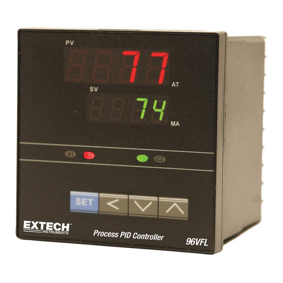
VFL Series PID Controllers
PV-Process Value
SV - Setting Value
AT - Auto tuning LED
MA - Manual mode LED
A1 - Alarm 1 LED
A2 - Alarm 2 LED
C1 - Control 1 LED
C2 - Control 2 LED
D
E
a
100
45
45+0.5
80
91
92+0.5
.com
b
c
d
45+0.5
60
48
92+0.5
120
96
48VFL & 96VFL v1.2
information@itm.com
07/13
Advertisement
Table of Contents

Related Manuals for Extech Instruments VFL Series


Summary of Contents for Extech Instruments VFL Series
- Page 1 VFL Series PID Controllers INSTRUCTION MANUAL ■FRONT PANEL DESCRIPTION: PV-Process Value SV - Setting Value AT - Auto tuning LED MA - Manual mode LED A1 - Alarm 1 LED A2 - Alarm 2 LED C1 - Control 1 LED C2 -...
-
Page 2: Wiring Diagram
WIRING DIAGRAM ■ ■Wiring Precautions: 1. Before wiring, verify the controller label for correct model number and options. 2. For thermocouple input, use the appropriate compensation wire. And note the polarity of input signal. 3. To avoid noise induction, keep input signal wires away from instrument power lines, load lines and power lines of other electrical equipment. - Page 3 ■ PROGRAMMING LEVEL PARAMETERS ■ lst. Prog. Level 2nd. Prog. Level 3rd. Prog. Level Prog. Level . Prog. Level 1. When 2nd Output (Cooling) is not selected, CPb、Cti、 Ctd、HYS2 and db parameters are not available. 2. When Pb≠0.0, HYS1 will be skipped. 3.
-
Page 4: User Level
■PARAMETER DESCRIPTION: LEVEL Selection Press keys for at least 5 seconds to access Soft Level. Use key to select programming level. Then press key to enter this level. Description LEVEL SoFt Level PID Level Option Level USER LEVEL CODE DESCRIPTION RANGE Default LoLt -... - Page 5 adjust this parameter to better suit the application. When PB=0.0, this parameter will be not available. When set to zero, Pb & td ≠ 0 for PD control Derivative (Rate). This value is automatically calculated by activating the Auto tune function. If desired, the user can later 0-900sec adjust this parameter to better suit the application.
-
Page 6: Option Level
OPTION LEVEL CODE DESCRIPTION RANGE Default Input type selection. RANGE(℃) RANGE(℉) tYPE -50 ~ 1000 -58 ~ 1832 -50 ~ 1370 -58 ~ 2498 -270 ~ 400 -454 ~ 752 -50 ~ 750 -58 ~ 1382 Refer to figure. 0 ~ 1800 32 ~... -
Page 7: Alarm Function
dif.L, bd.Hi, bd.Lo If A2FU=None, it means alarm function is cancelled. t.on, t.oFF none, Stdy, Alarm 2 mode. Refer to alarm mode section for details Lath, St.La Controller address. For use with PC RS-485 interface 0 - 255 Baud rate. 2.4k=2400bps, 4.8k=4800 bps, 9.6k=9600 bps, 2.4k, 4.8k 9.6k 19.2k=19200 bps... - Page 8 A1MD/A2MD DESCRIPTION Normal alarm mode/ When timer function is selected, with the PV<SV, the timer function is disabled Standby mode When selected, in any alarm function, an alarm on power-up is prevented. The alarm is enabled only when the process value reaches the alarm set point.
- Page 9 The controller can also be set to ON/OFF, PI, PD and P control mode. Set Pb = 0 for ON/OFF control mode. Set ti = 0 for PD control mode. Set td = 0 fro PI control mode and ti, td = 0 fro P control mode.
- Page 10 Symptom Probable Solution - Sensor break error - Replace sensor - Sensor not connected - Check that the sensor is connected correctly - Unit must be repaired or replaced - A/D converter damage - Check for outside source of damage such as transient voltage spikes - Auto tune time out error Set Pb, ti, td manually...
-
Page 11: Controller Overview
Controller Overview Controller Wiring The controller must be wired before use. The controller’s input, outputs, and AC power are connected via its rear terminals. Refer to the wiring diagram for details. Programming Menus The controller uses a menu-based programming format. The menu levels are USER, PID, OPTION, and SOFT-START. -
Page 12: Specifications
Specifications General Specifications Display Dual 7-segment 4-digit LED: Red digits for Process Variable (PV) and green digits for Setpoint Variable (SV) Display range -1999 to 9999 Indicating accuracy ± (0.2% full scale + 1 digit) Display update rate 4 readings per second Output status indication Front panel Alarm (A1 and A2) and Control (C1 and C2) status LED’s inform the user when an output switches on or off. - Page 13 RTD Input Specifications RTD type Platinum 100 (DIN or JIS) RTD range -328 to 1202 F (-200 to 650 Break protection Up- and down-scale Lead wire effect 0.015 / Ohm Repeatability Analog (Linear) Input Specifications Current Input 4 to 20mA DC (2.7 input impedance) Voltage Input 1 to 5V DC (>10M...
Need help?
Do you have a question about the VFL Series and is the answer not in the manual?
Questions and answers