Table of Contents
Advertisement
Quick Links
F9.63 Flow Monitor and Transmitter
INSTRUCTION MANUAL
Table of Contents
1. Introduction............................................................................ 3
1.1.
Safety Instructions......................................................................... 3
1.2.
Unpacking..................................................................................... 3
2. Description............................................................................. 4
2.1.
Design.......................................................................................... 4
2.2.
Technical Features........................................................................ 4
2.3.
Connection to FlowX3 Sensors....................................................... 5
3. Specifications......................................................................... 5
3.1.
Technical Data.............................................................................. 5
3.2.
Dimensions.................................................................................. 6
4. Installation............................................................................. 7
4.1.
Location........................................................................................ 7
4.2.
Wiring.......................................................................................... 8
5. Operational Overview.............................................................. 11
5.1.
Keypad Functions......................................................................... 11
5.2.
General Operation Flowchart.......................................................... 11
6. View Level.............................................................................. 13
7. Menu Directory Level............................................................... 14
7.1.
Free access (no password required)................................................ 14
7.2.
Password protected access............................................................ 14
1
F9.63 Electromagnetic insertion flow sensor
EN 10-11
Advertisement
Table of Contents

Related Manuals for FLS FLOWX3 F9.63


Summary of Contents for FLS FLOWX3 F9.63
-
Page 1: Table Of Contents
F9.63 Flow Monitor and Transmitter INSTRUCTION MANUAL EN 10-11 Table of Contents 1. Introduction…………………………………………………………………. 3 1.1. Safety Instructions………………………………………………………………. 3 1.2. Unpacking…………………………………………………………………………. 3 2. Description………………………………………………………………….. 4 2.1. Design……………………………………………………………………………... 4 2.2. Technical Features……………………………………………………………… 4 2.3. Connection to FlowX3 Sensors………………………………………………. 5 3. Specifications………………………………………………………………. 5 3.1. - Page 2 8. Menu and Edit Level………………………………………………………. 15 8.1. Calibration Menu…………………………………………………………………… 15 8.1.1. Unit………………………………………………………………………………. 15 8.1.2. K-Factor…………………………………………………………………………. 16 8.1.3. Size…………………………………………………………………………………16 8.2. Output Menu………………………………………………………………………… 17 8.2.1. 4 – 20mA Output……………………………………………………………….. 17 8.2.2. O.C. Output (OPT)……………………………………………………………… 18 8.2.2.1. O.C. Output (OPT): MIN mode…………..…………………………….… 18 8.2.2.2.
-
Page 3: Introduction
1. Introduction 1.1. Safety Instructions General Statements Do not install and service the instrument without following the Instruction Manual. This unit is designed to be connected to other instruments which can be hazardous if used improperly. Read and follow all associated instrument manuals before using with this instrument. -
Page 4: Description
DN15 (0.5”) to DN600 (24”). The FLS FlowX3 F9.63 offer an indication and a 4…20 mA signal for long distance transmission and it also provides one programmable open collector output and two relay outputs. -
Page 5: Connection To Flowx3 Sensors
2.3. Operating Principle If an electrical conductor is caused to move in a magnetic field, such movement induces a voltage in the conductor ( Faraday’s law ). The magnetic coil in the body of the instrument generates a magnetic field perpendicular to the flow direction. The magnetic field and the velocity induce a voltage between the electrodes. -
Page 6: Dimensions
Relay output: o User selectable as MIN alarm, MAX alarm, Window alarm, Pulse Out, Off o Mechanical SPDT contact o Max pulse/min: 180 o Hysteresis: User selectable Environmental Storage Temperature: -10°C to +60°C (14°F to 140°F) Ambient Temperature: 0°C to +60°C (32°F to 140°F) ... -
Page 7: Installation
4. Installation 4.1. Location Different pipe configurations and obstacles in the flow line such as valves, elbows, pipe bends and strainers create variations on the flow profile. Whenever possible follow the EN ISO 5167-1 installation recommendations to locate the sensor. Always maximize distance between flow sensor and pump. -
Page 8: Wiring
In gravity-flow systems the connection to the tank must be designed so the level does not drop below the outlet: this to avoid pipe to draw air in from the tank causing an erratic measurement of the Magmeter. 4.4. Wiring All wiring connections to F9.63 are made via removable terminals. - Page 9 Rear Terminal View Power / Loop Wiring Diagram Stand-alone application, Connection to a PLC with built-in no current loop used power supply (3 wire connection) Connection to a PLC / Instrument with ONE separate power supply F9.63 Electromagnetic insertion flow sensor...
- Page 10 Connection to a PLC / Instrument with TWO separate power supplies Open Collector Wiring Diagram Connection to a PLC Connection to a PLC / Instrument Open Collector input digital input with separate Power Supply Connection to FlowX3 Instruments Relay Wiring Diagram The alarm is OFF during normal operation The alarm is ON during normal operation and goes ON according to Relay settings.
-
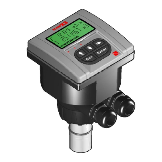
Page 11: Operational Overview
5. Operational Overview The FLOWX3 NEW F9.63M Insertion Magmeter like all members of X3 Line, features a digital display and a five-button keypad for system set-up, calibration and operation. This section contains a description of the keypad functions and the general operation flowchart of the instrument. - Page 12 F9.63 Electromagnetic insertion flow sensor...
-
Page 13: View Level
6. View Level During normal operation, the flow monitor and transmitter is in View Level displaying all measured values and the status of the analog output, O.C. and Relay output. If the flow monitor is in a different level and no activity occurs for more than 3 minutes, it will return to View Level. -
Page 14: Free Access (No Password Required)
7.1. Free access (no password required) 7.2. Password protected access F9.63 Electromagnetic insertion flow sensor... -
Page 15: Menu And Edit Level
8. Menu and Edit Levels 8.1. Calibration Menu The F9.63 basic settings are made in this menu: To set flow rate and totalizer Engineering Units To set K-Factor To set K-Factor 8.1.1. Unit Set the engineering units for the instant flow rate and the total flow rate. All the options available are displayed on the LCD. -
Page 16: K-Factor
8.1.2. K-Factor Set the K-Factor to tell the monitor and transmitter how to convert the input frequency from the flow sensor into a flow rate. The K-factor is unique to the sensor model and to the pipe size and material. Refer to section 10. -
Page 17: Output Menu
8.2. Output Menu The F9.63 analog and digital output are set-up in this menu: To set 4 – 20mA Loop Output value To set OPT Open Collector Output mode To set R1 Relay Output mode To set R2 Relay Output mode 8.2.1. -
Page 18: Output (Opt)
8.2.2. O.C. Output (OPT) The mode of operation for the Open Collector Output (OPT) can be selected between different options: MIN alarm, MAX alarm, Window or volumetric Pulse. The signal can be disabled (set to OFF) if not used. If the O.C. Output is programmed the OPT icon will appear on the third line of the display. -
Page 19: Output (Opt): Max Mode
8.2.2.2. O.C. Output (OPT): MAX mode output triggers when the flow rate greater than the setpoint: placed below icon will switch on. The output will relax when the flow rate drops below setpoint plus the hysteresis value. Flow Setpoint Hysteresis Time output relaxed output energized... -
Page 20: Output (Opt): Pulse Mode
8.2.2.4. O.C. Output (OPT): PULSE mode In PULSE mode the O.C. output will generate a pulse when the set volume passes the sensor. ENTER any value from 0.0001 to 99999. The duration of the pulse can be chosen from 000.1 to 999.9 seconds. 8.2.3. -
Page 21: R1 Output (Out1): Min Mode
8.2.3.1. R1 Output (OUT1): MIN mode output triggers when flow rate drops below the setpoint: placed below OUT1 icon will switch on. The output will relax when the flow rate moves above setpoint plus the hysteresis value. Flow Hysteresis Setpoint Time output relaxed output energized... -
Page 22: R1 Output (Out1): Window Mode
8.2.3.3. R1 Output (OUT1): WINDOW mode output triggers when the flow rate greater than the max setpoint or when flow rate drops below the min setpoint: placed below R1 icon will switch The output will relax when the flow rate between the two setpoint ±... -
Page 23: Simulation Menu
8.3. Simulation Menu The F9.63 analog and digital output can be simulated and tested in this menu: To manually test the output current loop To manually toggle OPT output To manually toggle OUT1 output To manually toggle OUT2 output 8.3.1. Test 4 – 20mA Loop Manually simulate output... -
Page 24: Test O.c. Output (Opt)
8.3.2. Test O.C. Output (OPT) Manually toggle the status of the Open Collector (OPT) output for testing 8.3.3. Test R1 Output (OUT1) Manually toggle the status of the Relay R1 (OUT1) output for testing R1 Output (OUT1) test repeats for R2 Output (OUT2) F9.63 Electromagnetic insertion flow sensor... -
Page 25: Options Menu
8.4. Options Menu To adjust LCD contrast To select the averaging level of LCD, output and relay response To set the flow rate decimal point position To set the totalizer decimal point position To adjust the minimum current output To adjust the maximum current output To set ON or OFF password protection to enter Menu Levels... -
Page 26: Filter
8.4.2. Filter Select the averaging level to dampen LCD indication, output and relay response. OFF: dampening effect, near instantaneous response. 8.4.3. Flow Decimal Point Set the decimal point position to get the best resolution application. Select following options: X.XXXX XX.XXX XXX.XX XXXX.X XXXXX. -
Page 27: Total Decimal Point
8.4.4. Total Decimal Point Set the decimal point position to get the best resolution application. Select one following options XXXXXXXX.XX XXXXXXXXX.X XXXXXXXXXX. 8.4.5. Loop Adjust 4mA This option can be used to modify the basic 4mA setting to match the transmitter output to any external device. -
Page 28: Loop Adjust 20Ma
8.4.6. Loop Adjust 20mA This option can be used to modify the basic 20mA setting to match the transmitter output to any external device. Increment output current value by pressing UP arrow key or decrement it by pressing DOWN arrow key. 8.4.7. -
Page 29: Restot Pwd
8.4.8. Restot PWD Set ON the Restot PWD to protect resettable totalizer from undesired reset operations. NOTE: the standard password is and it cannot be modified. 8.4.9. Language This option offers to select the display language F9.63 Electromagnetic insertion flow sensor... -
Page 30: K-Factor Calculate
8.4.10. K-Factor Calculate Option used to perform automatic calculation of K-Factor by measuring the volume filled into a tank. This to get the highest accuracy possible. Press ENTER to start calculation. Switch on a pump or open a valve. F9.63 starts counting pulses from the sensor. -
Page 31: Troubleshooting
9. Troubleshooting The instrument correctly installed is maintenance-free. The case and the front panel can be cleaned with soft cloth and an appropriate cleaning agent. 9.1. Display messages F9.63 Electromagnetic insertion flow sensor... -
Page 32: K-Factor Tables
10.K-Factor Table ( only for frequency output ) K-Factor is the number of pulses a sensor produces for one liter of fluid measured. Here all K-Factors for water at ambient temperature are listed. K-Factor values can depend upon the installation conditions. Please contact your dealer for K-Factor values not included in the table. - Page 33 NPT Female Threaded PVC Tee Fittings for ASTM SCH. 80 PVC Tee Fittings for ASTM SCH. 80 pipes ASTM SCH. 80 pipes (NPT threaded female ends) (female ends for solvent welding) Part No. SIZE K-Factor F.S. l/s Part No. SIZE K-Factor F.S.
- Page 34 Installation on C-PVC pipes ISO Metric CPVC Tee Fitings for ISO SDR 21 ISO Clamp Saddles for ISO SDR 21 pipes pipes (female ends for solvent welding) Part No. K-Factor F.S. l/s Part No. K-Factor F.S. l/s SCIC063BVC 50 39,88 12,54 TFIC20B 462,04...
- Page 35 ISO Clamp Saddles for ISO SDR 21 pipes NPT Female Threaded PP Tee Fittings for ASTM SCH.80 pipes (NPT threaded female ends) Part No. K-Factor F.S. l/s SCIC063BME 50 42,40 11,79 Part No. K-Factor F.S. l/s SCIC075BME 65 29,86 16,75 SCIC090BME 80 20,71 24,14...
- Page 36 Installation on PVDF pipes ISO Metric PVDF Tee Fittings for ISO SDR 33 pipes ISO Clamp Saddles for ISO SDR 33 pipes (female ends for socket welding) Part No. K-Factor F.S. l/s Part No. K-Factor F.S. l/s SCIC063BF 37,20 13,44 TFIF20B 510,01 0,88...
- Page 37 Special Installation on DN 250 and DN 300 pipes PVC Wafer Fittings PP Wafer Fittings Part No. K-Factor F.S. l/s Part No. K-Factor F.S. l/s WVIC280B 250 280 on request WFIC280B on request WVIC315B 300 315 on request WFIC315B on request WVIC280D 250 280 on request WFIC280D...
- Page 38 Correction formula for K-Factor calculation according to real internal diameter: K-Factor_NEW = (K-Factor x ID²) / ID_NEW² where: ID = Value in the table for the internal diameter (in mm) ID_NEW = New value for the real internal diameter (always in mm) K-Factor = Value in the table K-Factor_NEW = New K-Factor value for the specified internal diameter EXAMPLE:...
-
Page 39: Ordering Data
11.Ordering Data FLOWX3 NEW F9.63M.XX Part No. Power supply Length Body Electrodes O-rings Enclosure F9.63M.09 12-24 VDC 316L SS/PVDF 316L SS EPDM IP65 F9.63M.10 12-24 VDC 316L SS/PVDF 316L SS IP65 F9.63M.11 12-24 VDC 316L SS/PVDF 316L SS EPDM IP65 F9.63M.12 12-24 VDC 316L SS/PVDF... - Page 40 Electronic Replacements Item Part No. Name Description Magmeter electronic device with display, 4-20mA output, 2 relay F9.63M.SP1 Electronic device output and 1 open collector output for mono-directional sensor Magmeter mono- 316L SS/PVDF body - EPDM O- F3.63M.SP09 directional flow sensor Rings - L0 length Magmeter mono- 316L SS/PVDF body - FPM O-...
Need help?
Do you have a question about the FLOWX3 F9.63 and is the answer not in the manual?
Questions and answers