Table of Contents
Advertisement
Quick Links
Advertisement
Table of Contents

Related Manuals for FISNAR F1300N.2


Summary of Contents for FISNAR F1300N.2
- Page 1 F1300N.2 Rotary Table Operating Manual info@fisnar.com www.fisnar.com...
- Page 2 F1300N.2 Rotary Table Operating Manual Table of Contents Machine Overview Product Safety Statement Specifications Accessories External Controls Front • • Back HMI Controls Production Screen • • Test Screen • Machine Settings Screen Machine Setup Z-Axis Drive Cylinder Setup Dispense Setup...
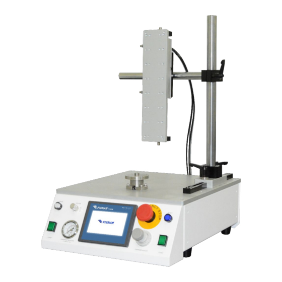
- Page 3 F1300N.2 Rotary Table Operating Manual OVERVIEW FIG. 1: Model F1300N.2 Rotary Table The F1300N.2 rotary table provides an efficient method of dispensing a circular pattern on areas that are difficult to access. The tilting Z-axis allows for controlled rotary dispensing at a fixed angle.
-
Page 4: General Precautions
F1300N.2 Rotary Table Operating Manual SAFETY General Precautions Do not operate the machine in excess of its maximum ratings / settings. Make sure the machine is connected to a properly grounded power source. Make sure that the input air supply is clean and dry. A 5 micron air filter/regulator (item number 560567) is supplied and recommended to use, so as to ensure the input air supply is clean and dry. -
Page 5: Inappropriate Use
Immediately disconnect power if any sparking or smoke appears. Do not expose the machine directly to sunlight. Maintenance The F1300N.2 is generally a maintenance free machine. However, to ensure smooth operation please follow the below instructions. Only use non-woven cleaners on the machine. -
Page 6: Specifications
F1300N.2 Rotary Table Operating Manual SPECIFICATIONS Dimensions (W x D x H): 13.8” x 19” x 22.6” (350 x 482 x 574 mm) Weight: 24.3 lbs (11 kg) Input AC to Power 100 – 240 VAC, 50 / 60 Hz... -
Page 7: External Controls
F1300N.2 Rotary Table Operating Manual EXTERNAL CONTROLS FIG. 2: External Controls Overview - Front Item Illustration Item Illustration Item Illustration Purge Button Reset Button HMI Display Air Pressure Regulator Vacuum Control Knob Start Button Emergency Stop Button Air Pressure Gauge Start Button ©... - Page 8 F1300N.2 Rotary Table Operating Manual Press the purge button to manually dispense fluid material from the syringe barrel or cartridge. Purge Button Or, if using a pneumatic dispense valve, press the purge button to manually actuate the dispense valve. This feature is only needed if dispensing a low viscosity fluid directly from a syringe barrel (I.E.
- Page 9 F1300N.2 Rotary Table Operating Manual The HMI display is used to, Enter the parameters of the program cycle. Manually actuate individual components of the machine. HMI Display Adjust machine settings. For full information on the HMI Display functions please refer to “HMI Controls”...
- Page 10 F1300N.2 Rotary Table Operating Manual EXTERNAL CONTROLS FIG. 3: External Controls Overview - Back Item Illustration Item Illustration Item Illustration On / Off Switch Cylinder Out Port Sensor Connector Foot Switch Fuse Dispense Air Out Port Connector I/O Connector USB Connector Exhaust Port Ext.
- Page 11 F1300N.2 Rotary Table Operating Manual On / Off Switch Used to switch the machine on or off. Fuse A 2.5A fuse is located here to protect the internal electrical circuit. Where the external machine I/O input signals and output signals are connected.
- Page 12 F1300N.2 Rotary Table Operating Manual At the start of a dispensing cycle, the regulated compressed air set by the pressure regulator and displayed on the pressure gauge on the machine will exit this port. It is used to pressurize and dispense the fluid material from the connected syringe barrel or cartridge during the program cycle.
- Page 13 F1300N.2 Rotary Table Operating Manual Exhaust Port At the end of a program cycle, pressurized air that was used to control the (4mm OD) program cycle will be exhausted from this Exhaust Port. External Compressed air 70-100 psi (5-7 bar) is to be connected here.
- Page 14 F1300N.2 Rotary Table Operating Manual HMI CONTROLS FIG. 4: HMI Controls Overview – Production Screen Item Illustration Item Illustration Item Illustration Cycle Counter Operation Mode Machine Settings Home Button Program Number Production Screen Static Mode Test Screen Stop Button © 2022 Fisnar - 14 - F1300N.2 Rev 01...
- Page 15 F1300N.2 Rotary Table Operating Manual Displays the number of program cycles that have taken place since the Cycle Counter cycle counter was last reset in the Machine Settings screen. Program Displays the program number the machine is executing. The program Number number is selected in the Machine Settings screen.
- Page 16 F1300N.2 Rotary Table Operating Manual Once the password has been entered, touch the “Enter” button on the dialogue window. The pop-up dialogue window will then automatically disappear. The user can then touch the “Enter” button on the original pop- up message.
- Page 17 F1300N.2 Rotary Table Operating Manual Once the password has been entered touch the “Enter” button on the dialogue window. The pop-up dialogue window will then automatically disappear. The user can then touch the “Enter” button on the original pop- up message.
- Page 18 F1300N.2 Rotary Table Operating Manual HMI CONTROLS FIG. 5: HMI – Test Screen Item Illustration Item Illustration Item Illustration Glue Light Cylinder Down Light Motor Button Home Light Motor Light Glue Button Cylinder Up Light Cylinder Button Spray Button © 2022 Fisnar - 18 - F1300N.2 Rev 01...
- Page 19 F1300N.2 Rotary Table Operating Manual When the “Glue” button is in the “ON” position, the Glue Light will light up green. When the light is green in color the dispense solenoid is active and Glue Light the machine is sending the signal to dispense fluid material from the syringe barrel/cartridge or actuate the connected dispense valve.
- Page 20 F1300N.2 Rotary Table Operating Manual HMI CONTROLS FIG. 6: HMI - Machine Settings Item Illustration Item Illustration Item Illustration E-Stop Condition Change Test Password Cycle Count Limit Firmware Version Change Setup Password Current Cycle Count Total ON Time Operation Mode...
- Page 21 F1300N.2 Rotary Table Operating Manual This button is used to confirm the behavior of the Z-Axis drive cylinder when the E-Stop button is pressed as described below. E-Stop Up button highlighted with a green color background If the E-stop button is pressed while the Z-Axis is moving to the “DOWN”...
- Page 22 F1300N.2 Rotary Table Operating Manual Sets a password to access the “TEST” screen. Change Test Password The machine is shipped without a password. The master override password is 347627. Sets a password to access the “Machine Settings” screen. Change Setup Password The machine is shipped without a password.
- Page 23 F1300N.2 Rotary Table Operating Manual Displays the total number of completed program cycles made by the Current Cycle machine. Count This counter is resettable. Touch and hold down the “Reset Count” button for 2 seconds to reset the Reset Count “Current Cycle Count”...
-
Page 24: Machine Setup
F1300N.2 Rotary Table Operating Manual MACHINE SET UP FIG. 7: Machine Setup To meet the conformity requirements of the European Community (CE) Machinery Safety Directive (2006/42/EC) or UK (UKCA) Machinery (Safety) Regulations 2008 place the machine into an appropriate safety enclosure. - Page 25 F1300N.2 Rotary Table Operating Manual Insert the electrical connector on the Z-Axis drive assembly into the “Safety” port on the back of the machine. Connect pneumatic tubing marked “Cylinder In” on the Z-Axis drive assembly to the “Cylinder In” port on the back of the machine.
- Page 26 F1300N.2 Rotary Table Operating Manual Z-AXIS DRIVE CYLINDER SETUP FIG. 8: Z-Axis Drive Cylinder Setup The machine is supplied with the Z-Axis drive cylinder set at a pre-set (recommended) speed. The upward and downward speeds are controlled by flow regulators integrated into the push-in fittings where the “Cylinder In”...
- Page 27 F1300N.2 Rotary Table Operating Manual To test the, Downward Speed: Touch the “Cylinder” button on the HMI so it changes to “ON”. The Z-Axis drive assembly will move downwards to the “DOWN” position. Upward Speed: Touch the “Cylinder” button on the HMI so it changes to “OFF”.
- Page 28 DISPENSE SETUP FIG. 9: Dispense Setup The F1300N.2 Rotary Table is a versatile machine and therefore capable of having a variety of different dispense equipment systems mounted onto and incorporated into it. The setting up of the machine will therefore differ according to the selected configuration and dispense application.
- Page 29 F1300N.2 Rotary Table Operating Manual Insert the syringe barrel into the syringe barrel holder. Secure in place by gently rotating the upper locking screw of the syringe barrel until the syringe barrel is held securely in place with minimum pressure.
- Page 30 F1300N.2 Rotary Table Operating Manual Install the workpiece onto the machine that is to have fluid material dispensed onto it. Maneuver the dispense tip into the required dispense location on the workpiece by first loosening the clamping levers on the Z-Axis drive assembly, horizontal bar assembly and vertical bar assembly.
-
Page 31: Operation Modes
F1300N.2 Rotary Table Operating Manual OPERATION MODES FIG. 10: Standard Mode STANDARD MODE Standard Mode allows the machine to dispense a single continuous circular fluid bead onto a workpiece. Touch the button to enter the “Machine Settings” screen and touch the operation mode button until the button displays the text “Standard Mode”. - Page 32 F1300N.2 Rotary Table Operating Manual Rotation Delay: Sets the time (seconds) before the motor starts rotating, once the Z-Axis drive cylinder reaches the “DOWN” position. Fluid material is dispensed during the rotation delay time. This parameter can be used, when dispensing micro fluid beads and there is a need to ensure the Z- Axis drive cylinder is in an absolute stationary position before fluid is dispensed onto the workpiece.
- Page 33 F1300N.2 Rotary Table Operating Manual A pop-up dialogue window will automatically appear allowing the user to type in the desired value. Once the value has been entered, touch the “Enter” button on the dialogue window. The pop-up dialogue window will then automatically disappear, and the value will be automatically saved and displayed in the parameter value cell.
-
Page 34: Pulse Mode
F1300N.2 Rotary Table Operating Manual OPERATION MODES FIG. 11: Pulse Mode PULSE MODE Pulse Mode allows the machine to dispense multiple dots / arcs within a single circular pattern on a workpiece. Touch the button to enter the “Machine Settings” screen and touch the operation mode button until the button displays the text “Pulse Mode”. - Page 35 F1300N.2 Rotary Table Operating Manual Gap Angle: Sets the angle (degrees) duration that the motor will continue to rotate for after the “Pulse Angle”. No fluid material is dispensed during the gap angle. Rotation Delay: Sets the time (seconds) before the motor starts rotating, once the Z-Axis drive cylinder reaches the “DOWN”...
- Page 36 F1300N.2 Rotary Table Operating Manual A pop-up dialogue window will automatically appear allowing the user to type in the desired value. Once the value has been entered, touch the “Enter” button on the dialogue window. The pop-up dialogue window will then automatically disappear, and the value will be automatically saved and displayed in the parameter value cell.
- Page 37 F1300N.2 Rotary Table Operating Manual OPERATION MODES FIG. 12: Index Mode INDEX MODE index Mode allows the machine to dispense onto a workpiece in a fixed position for a set period of time, before indexing to another position at a set angle.
- Page 38 F1300N.2 Rotary Table Operating Manual Dispense Time: Sets the time (seconds) that fluid material will be dispensed for. Tail Time: Sets the time (seconds) that the Z-Axis drive cylinder will remain in the “DOWN” position at the end of the “Dispense Time”, before moving to the “UP”...
- Page 39 F1300N.2 Rotary Table Operating Manual A pop-up dialogue window will automatically appear allowing the user to type in the desired value. Once the value has been entered, touch the “Enter” button on the dialogue window. The pop-up dialogue window will then automatically disappear, and the value will be automatically saved and displayed in the parameter value cell.
-
Page 40: Warning Messages
F1300N.2 Rotary Table Operating Manual WARNING MESSAGES FIG. 13: Emergency Stop Emergency Stop The pop-up message is automatically displayed in the event that the Emergency Stop button on the front panel of the machine is pressed, or the external E-Stop circuit on the EXT. connector changes to an “open”... - Page 41 F1300N.2 Rotary Table Operating Manual WARNING MESSAGES FIG. 14: Door Open Door Open The pop-up message is automatically displayed in the event that the Door Circuit on the EXT. connector (controlling the safety light curtain or door switch) has been broken and changes to an “open”...
- Page 42 F1300N.2 Rotary Table Operating Manual WARNING MESSAGES FIG. 15: Reset Machine Reset Machine In the event that the “STOP” button on the HMI display screen is touched or when the Emergency Stop button on the front of the machine is released, the pop-up message is displayed requesting for the machine to be reset.
- Page 43 F1300N.2 Rotary Table Operating Manual WARNING MESSAGES FIG. 16: Home Machine Home Machine The pop-up message is automatically displayed when the “RESET” button on the front panel of the machine or the reset button connected to the EXT. connector is pressed The pop-up message will dissappear when, The “HOME MACHINE”...
- Page 44 F1300N.2 Rotary Table Operating Manual WARNING MESSAGES FIG. 17: Alarm In Alarm In The pop-up message is automatically displayed when the “Alarm-in” circuit on the I/O connector is activated. The pop-up message will automatically disappear when the “Alarm-in” circuit on the I/O connector is deactivated.
- Page 45 F1300N.2 Rotary Table Operating Manual WARNING MESSAGES FIG. 18: Machine Not in Start Position Machine Not in Start Position The pop-up message is displayed in the event that the Z-Axis drive cylidnder is not in the correct start position, when a program cycle is initiated.
- Page 46 F1300N.2 Rotary Table Operating Manual WARNING MESSAGES FIG. 19: Cycle Count Limit Cycle Count Limit If using the Cycle Cout limit function, the pop-up message is automatically displayed when the cycle count limit value is reached. The pop-up message will dissappear when, The two green start buttons on the front panel of the machine are pushed.
- Page 47 F1300N.2 Rotary Table Operating Manual EXTERNAL DISPENSER ACTUATION FIG. 20: External Dispenser Actuation A dry contact closure (0 Volt) between Normally Open (Pin #1) and Common Output (Pin #2) will trigger a dispense signal to be initiated on an external dispense controller.
- Page 48 F1300N.2 Rotary Table Operating Manual EXT. CONNECTOR Pin# Description Start Signal Door Switch (COM) Door Switch (NC) Reset Emergency Stop In Emergency Stop Out +24V DC Purge Signal FIG. 21: Ext. Connector PLEASE READ: When the Ext. Connector is not connected to an external start/stop box, the “SHORTED”...
-
Page 49: Safety Connector
F1300N.2 Rotary Table Operating Manual SAFETY CONNECTOR Safety Connector (included) Pin# Description Brown TX – 24V DC Blue TX – 0V DC Brown RX – 24V DC Blue RX – 0V DC Black RX – OSSD1 White RX – OSSD2 FIG. - Page 50 F1300N.2 Rotary Table Operating Manual INTERNAL SAFETY RELAY Safety Relay Wiring Kit (included) I.D / Pin# Color Safety Relay Pin# Power / 1 Blue Power / 2 Black Door / 1 Black Door / 2 White Con 6 / 1...
- Page 51 F1300N.2 Rotary Table Operating Manual I/O CONNECTOR Pin # Function Power +ve (24V DC) Power -ve (0V DC) Alarm IN Alarm IN (GND) Alarm OUT Alarm OUT (GND) Start Signal / Initialize IN Start Signal / Initialize IN (GND) Machine Busy OUT...
-
Page 52: Output Signals
F1300N.2 Rotary Table Operating Manual OUTPUT SIGNALS Output Type: Open Collector Photocoupler (NPN) Output Power: Output signals are able to sink a maximum of 250 milliamps per pin. Output Function: When the output signal is activated, the circuit between the output pin (pin #5, 9, 11 &... - Page 53 F1300N.2 Rotary Table Operating Manual OUTPUT SIGNAL DEFINITION Pin #5 Alarm Out (Output): The signal will be activated if any one of the below conditions occur. o If the “Alarm In” input circuit has been activated. o If the Emergency Stop Button has been pressed.
- Page 54 F1300N.2 Rotary Table Operating Manual INPUT SIGNAL DEFINITION Pin #3 Alarm In (Input): When connected to a GND pin the “Alarm In” signal will be activated, resulting in the “Alarm Out” signal (Pin #5) being activated automatically. Pin #7 Start Signal / Initialize IN (Input): When connected to a GND pin the “CC Initialize”...
-
Page 55: Spare Parts List
F1300N.2 Rotary Table Operating Manual SPARE PARTS LIST © 2022 Fisnar - 55 - F1300N.2 Rev 01... - Page 56 F1300N.2 Rotary Table Operating Manual SPARE PARTS LIST Ref. Item Number Description A08SWOT-D16LMT2R Start Button 1705-10240004 Front Panel A08PSW-P16LMR2-1ABOW Purge Button 1705-10240004 HMI Display Screen 1211-10900003 Emergency Stop Sticker A08PSW-D16LMR2-1ABOB Reset Button A08PSW-A22EM11R Emergency Stop Button 1705-10400002 Solenoid Valve – Air Cylinder Drive...
- Page 57 F1300N.2 Rotary Table Operating Manual MACHINE DRAWING © 2022 Fisnar - 57 - F1300N.2 Rev 01...
- Page 58 F1300N.2 Rotary Table Operating Manual Z-AXIS TOOLING PLATE DRAWING © 2022 Fisnar - 58 - F1300N.2 Rev 01...
- Page 59 F1300N.2 Rotary Table Operating Manual TURNTABLE DRAWING © 2022 Fisnar - 59 - F1300N.2 Rev 01...
-
Page 60: Maintenance
F1300N.2 Rotary Table Operating Manual MAINTENANCE It is essential to inspect and maintain the machine to prevent unexpected failures or malfunctions, thus ensuring safe operation and maximizing the machines life correctly and periodically. The external parts of the machine should be kept clean at all times. Use a soft cloth to clean the machine. - Page 61 F1300N.2 Rotary Table Operating Manual Remove objects causing instability. Rotary table is Check that all rubber anti- Stability unstable / not-sitting vibration feet are in place. flat. Relocate machine to a flat surface. Check for and remove debris Motor is running around the turntable.
-
Page 62: Troubleshooting
F1300N.2 Rotary Table Operating Manual TROUBLESHOOTING Ways to adapt the quality and finish of the dispense process are described below. An increase in the dispense pressure will increase the flow rate of the fluid material being dispensed from the syringe barrel, cartridge or valve being used for the application. - Page 63 F1300N.2 Rotary Table Operating Manual NOTES © 2022 Fisnar - 63 - F1300N.2 Rev 01...
-
Page 64: Limited Warranty
In no event shall manufacturer be liable for consequential or incidental damages. A return authorization is required prior to shipping a defective machine to the factory. Manufacturer reserves the right to make engineering or product modifications without notice. info@fisnar.com www.fisnar.com...
Need help?
Do you have a question about the F1300N.2 and is the answer not in the manual?
Questions and answers