Lamtec BT300 BurnerTronic Manual
Hide thumbs
Also See for BT300 BurnerTronic:
- Quick reference (48 pages) ,
- Manual (210 pages) ,
- Quick reference (34 pages)

Related Manuals for Lamtec BT300 BurnerTronic


Summary of Contents for Lamtec BT300 BurnerTronic
- Page 1 Manual BT300 BurnerTronic Software versions BT300 v3.9 and UI300 V3.12 (HW V 1)/4.4 (HW V 2) Sensors and Systems for Combustion Engineering www.lamtec.de...
-
Page 3: Table Of Contents
Table of Contents Table of Contents Important Information about the Manual ........7 Validity of these Instructions . - Page 4 Table of Contents Actuator ............. 65 4.9.1 Operation after Power ON/Long RESET .
- Page 5 Table of Contents 6.3.4.1 Setpoint Graphic ..........124 6.3.4.2 Curve Table .
- Page 6 Table of Contents Variable Speed Drive Module VSM100 ........201 8.3.1 DIP Switch .
- Page 7 Table of Contents Disposal Notes ............244 EU Declaration of Conformity .
-
Page 8: Important Information About The Manual
Important Information about the Manual Validity of these Instructions This manual is valid for BT300 BurnerTronic in any configuration. The content of this document refers to software version BT300 v3.9 and UI300 V3.12 (HW V 1)/4.4 (HW V 2). Oth-er software versions may cause that some of the functions described in this document are not available or have another functionality as described in this document. - Page 9 Important Information about the Manual South Africa: SAGA Act 85 of 1993 PER R 734 -2009 Russia/Belarus/Kazakhstan: NOTICE Respect the national safety regulations and standards.
-
Page 10: General Safety Instructions
General Safety Instructions General Safety Instructions Classification of the Safety Instructions and Warnings The following symbols are used in this document to draw the user's attention to important safe- ty information. They are located at points where the information is required. It is essential that the safety information is observed and followed, and that applies particularly to the warnings. -
Page 11: Product-Specific Dangers
The BT300 is a safety device! The device must not be opened, interfered with or modified. LAMTEC assumes no liability for damages arising as a result of unauthorised interference! • After commissioning and after each maintenance action check the exhaust gas values across the entire power range. -
Page 12: Commissioning Notes
General Safety Instructions 2.2.1 Commissioning Notes • During commissioning it is essential to observe all safety accessory. • There is no way to completely rule out the connection plugs being connected incorrectly. For this reason, check the correct assignment of the plugs before commissioning the plant. -
Page 13: Basic Device
General Safety Instructions 2.2.1.2 Basic Device Check the following items prior to commissioning: • Valves must be assigned correctly to valve outputs on BT300. • Correct setting of time parameters. • Functioning of flame sensor – in case of flame blow-off during operation –... -
Page 14: Checking The Fuel/Air Ratio Control System
General Safety Instructions 2.2.2.2 Checking the Fuel/Air Ratio Control System Save setting values (curve parameters) for actuator elements, fuel and combustion air through the complete range of burner firing rate in sufficient number. Select setting values of fuel and combustion air considering combustion chamber pressure, fuel pressure, temperature and pressure of the combustion air in order to guarantee proper operation with adequate excess air through the entire range of burner firing rate. -
Page 15: Security Advice - Mounting
General Safety Instructions Security Advice - Mounting • Compliance with national safety regulations and standards is obligatory at all times. • During the assembly and installation process, you must meet the standard requirements of DIN VDE 0100, 0550 and DIN VDE 0722 NOTICE To mount the BT300 basic unit, use screw fittings with an M4 thread (UNC32) and a maximum tightening torque of 1.8 Nm for fastening all four fixing points. -
Page 16: Installation Notes
General Safety Instructions Installation Notes • Lay high-voltage ignition cable always separately and in safe distance from device and other cables. • Only trained, qualified personnel may open the BurnerTronic’s cover. • Observe local and national regulations when wiring the electric cables inside the burner. •... -
Page 17: Electrical Connection Flame Sensor
General Safety Instructions Electrical Connection Flame Sensor Interruptions and losses in signal transmission need to be minimised: • Do not wire the sensor cable with other cables. Flame signal is reduced through line capacities. Use a separate 7-pole cable. •... -
Page 18: Product Description
Product Description Product Description Functional Description BT300 combines the benefits of an electronic fuel/air ratio control system with up to three mo- torised actuator elements and optional modules like an analogue output for speed control of the combustion air fan with an electronic burner control unit. The leakage test, flame monitor- ing system, power control unit and (optional) CO/O controller for control and optimisation of an oil or gas-fired forced-draught burner are all integrated. -
Page 19: Life Cycle
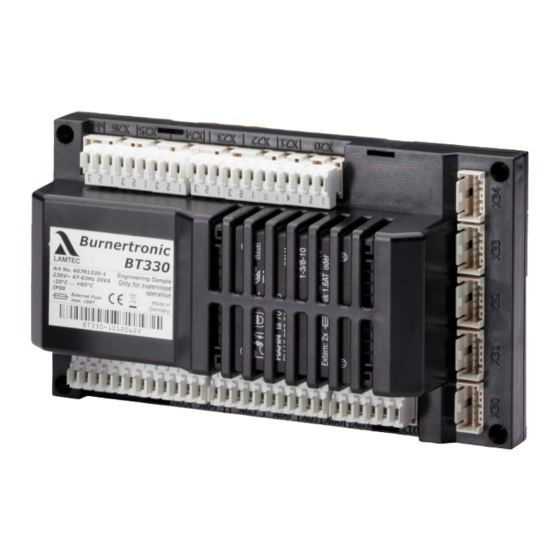
Product Description • BT341 Same range of functions as BT340 but also including following certificates: DIN EN 61508:2002 parts 1-7 for SIL 3 Performance Level PLE according DIN EN ISO 13849-1 Burner sequencer and fuel/air ratio control can be adjusted for a wide range of combustion conditions by setting parameters. - Page 20 Product Description 1 RAST5 plug connector optionally 2 RAST2.5 plug connector for actuator, User interface and LAMTEC SYSTEM BUS in cutting and clamping technique Fig. 3-2 Dimensions BT320 ... 341 (terminal assignment BT330/BT341 only)
- Page 21 Product Description Fig. 3-3 UI300 and Fig. 3-4 UI300 and dimensional drawings Fig. 3-5 UI300 panel cut-out...
- Page 22 Product Description Fig. 3-6 Additional cover IP65 for the User Interface Fig. 3-7 Dimensional drawing for IP65 Create a square cut-out and ensure that the burrs are removed. Hight 60 mm 2.36 in Width 107 mm 4.21 in Fig. 3-8 Dimensional drawing panel cut-out including mounting bore for the IP65 cover...
- Page 23 Product Description Function Power supply 230 V +10/-15 % 47-63 Hz 120 V +10/-15 % 47-63 Hz (on request) Maximum backup-fuse 10 A slow-blow To be used only in a grounded power line network! Power consumption max. 30 VA 1 A Switching threshold of ionisation cur- rent Digital signal inputs...
- Page 24 Product Description Display UI300-LSB Weight 149 g Power supply voltage via LSB Power consumption Flammability UL-94 V0 Cable length 2.5 m / 98.42" in Operating conditions Altitude above sea level 2000 m NHN without restriction 2000 m < z 5000 m NHN use possible with the following restrictions: - reduction of the maximum ambient temperature according to the diagram...
- Page 25 Product Description Fig. 3-9 Temperature derating BT300 for operation > 2000 m NHN...
-
Page 26: Actuator
Product Description 3.3.1 Actuator 3.3.1.1 Actuators 662R550... 1 15.4 (+0.3/-1) including axial play 2 Cap cannot be removed by hand 3 Flexible control cable (black), length 1.5 m 4 Plug connector (RAST 2.5) pole number 6 5 Brass tube and M4 x 30 DIN 912 cylinder bolt, tightening torque max. 1.5 Nm Function Power supply 24 VDC ±20%... - Page 27 Product Description Environmental conditions Operation Climatic condition Class 3K3 according to DIN EN 60721-3 Mechanical condition Class 3M3 according to DIN EN 60721-3 Temperature range -20 ... +60 °C (condensation is prohibited) Transport Climatic condition Class 2K3 according to DIN EN 60721-3 Mechanical condition Class 2M2 according to DIN EN 60721-3 Temperature range...
-
Page 28: Actuators 662R5001
Product Description 3.3.1.2 Actuators 662R5001... / 662R5003... Fig. 3-10 Dimensional drawing of servo motor type 662R5001-0 and 662R5003-0 without cable but with plug... - Page 29 Product Description Fig. 3-11 Dimensional drawing of servo motor type 662R5001-1 and type 662R5003-1 with cable Fig. 3-12 Dimensional drawing of servo motor type 662R5009-0 without cable but with plug...
- Page 30 Product Description Function 662R5001... 662R5003... 662R5009... Power supply 24 VDC ±20% Floating time 5 s/90° 5 s/90° 15 s/90° Direction of rotation 0° to 90° left - view to the drive shaft Effective 1.2 Nm (both directions of 3 Nm (both directions of 9 Nm (both directions output torque rotation)
-
Page 31: Flame Sensor/Flame Scanner
Product Description 3.3.2 Flame Sensor/Flame Scanner Fig. 3-13 KLC1000 Fig. 3-14 Dimensions KLC1000 (1 = radial scanning opening) KLC10/KLC1000 Input Data Power supply KLC10: 120 VAC -15/+10 % 50-60 Hz KLC1000: 230/240 VAC -15/+10 % 50-60 Hz Current consumption 5,5 mA Optical Evaluation Spectral range 185 - 260 nm... - Page 32 Product Description Fig. 3-16 Dimensions KLC2002 Fig. 3-15 Dimensions of angle adapter for KLC2002 KLC20/KLC2002 Input Data Power supply KLC20: 120 VAC -15/+10% 50-60 Hz KLC2002: 230/240 VAC -15/+10% 50-60 Hz Current consumption 3 - 4 mA Optical Evaluation Spectral range 380 - 1150 nm Design with optical filter 380 - 830 nm: Sensitivity max.
-
Page 33: Design And Functions
Design and Functions Design and Functions System Overview Fig. 4-1 System overview of BurnerTronic BT300... -
Page 34: Connecting Diagrams
Design and Functions Connecting Diagrams 4.2.1 Terminal assignment BT300 - Connection example X30 = User Interface UI 300 Maximum cable length X31 = LSB Option X01-X6+X08: 10 m X32 = continuous output 1, e.g. air damper X07+X09: 20 m X33 = continuous output 2, e.g. gas damper X10: 20 m 20 m... -
Page 35: Terminal Assignment Bt335 - Connection Example
Design and Functions NOTICE When running oil-solely burning applications, the function ’Oil pressure > min’ is aligned with X05. When running oil/gas burning applications (BT340 in combination with DFM300), the function ’Gas > min’ is aligned with X05. Put in oil/gas applications, the pressure monitoring for ’Oil pressure > min.’ in the oil safety interlock chain (SIC). -
Page 36: Optional Connections For The Fuel Line
Design and Functions WARNING! Conductors with max. 20 m cable length are allowed to have not more than 3 signal transfers in one cable, otherwise this would lead to dangerous malfunctions. Safety interlock chain is open but is detected as closed. NOTICE When running oil-solely burning applications, the function ’Oil pressure >... - Page 37 Design and Functions Fuel valve (gas side) Fuel valve (burner side) V3.1 Ignition valve (gas side) V3.2 Ignition valve (burner side) Gas pressure min sensor Actuator gas damper Alternative positioning of the pressure moni- tor P – if valve leakage check is not nec- essary.
-
Page 38: Optional Connections For The Flame Scanner
Design and Functions Oil pressure min sensor Oil valve for modulated operation, oil valve 1 stage at 2-stage operation Oil valve 2 stage at 2-stage operation Optional ignition valve Actuator for control valve oil/modulated opera- tion CPI/ Close Position Indicator (UK/AU) Prove Of Closure (US) ON switch at oil valve 1 which indicates that the valve is closed (option) - Page 39 Design and Functions Fig. 4-10 Connecting diagram F300K via power pack FN20 (also valid for F200K) Fig. 4-11 Connecting diagram F152 with FFS07/FFS08 Fig. 4-12 Connection F152 with FFS07/FFS08 to BT335...
- Page 40 Design and Functions Dimensional Drawings Fig. 4-13 Dimensional drawing F200K Fig. 4-14 Dimensional drawing F300K Fig. 4-16 Dimensional drawing KLC1000/KLC2002 side view Fig. 4-15 Dimensional drawing KLC1000/KLC2002 top view 1 Radial opening (with KLC1000 only)
-
Page 41: Lsb Module Integration
Design and Functions 4.2.5 LSB Module Integration EBM100 may be used as an alterna- tive field bus module instead of PBM100 Alternative CO/O measurement LEM100 can be used as an alternative to LCM100 to connect LSB to BT100 CO/O measurement Fig. - Page 42 2x2x0,50 twisted pairs with shielding, impedance 120 Devices on LAMTEC SYSTEM BUS (LSB) must be connected in serial/row (see Fig. 4-18 Se- rial BUS connection). The first and the last participant on LSB must be terminated with a ter- mination resistor of 120 . All the other BUS participants are not allowed to be connected to any termination resistor at all.
-
Page 43: Flame Monitoring
The following types of flame sensor for intermittent operation (burner switched off at least once every 24 hours) are valid for use. Manufacturer Type Settings P 800 Approval LAMTEC F152 with FFS07 o. FFS08 UV (up to v3.1) Continuous contact (from v3.3) F200K with FN20 UV (up to v3.1) -
Page 44: Flame Sensors
Design and Functions NOTICE For continuous operation, connect following types of flame sensors to BurnerTronic BT330 and BT340: Flame scanners with ionisation electrode Flame monitor for continuous operation with potential-free contact e.g. F200K. The fastening system must be designed in a way that unintentional detachment of the flame monitor is prevented. - Page 45 Design and Functions Before working on the flame detector, switch off the power supply. Before first commissioning or replacement of the device, check external wiring! Mounting Instructions The KLC 20/KLC 2002 should be mounted close to the flame with straight alignment using the Mounting Flange KLC or another suitable holder with Ø0.551 inch (14 mm) opening.
-
Page 46: Klc 10/Klc 1000
Design and Functions Viewing Angel Adapter KLC for radial adjustment Radial adjustment of the KLC2002 to the flame axis is possible with the optional view- ing angle adapter, which can replace the Mounting Flange KLC. An optionally available angle adapter provides the radial adjustment to the flame axis of KLC2002 by an optimally shaped reflector surface. - Page 47 Design and Functions impact shock, excessive moisture, or other problems rendering it inoperable. Repair work must never be attempted and is strictly forbidden by the relevant European Standards. WARNING! Prior to commissioning the unit; carefully check that the wiring connections have been made correctly.
-
Page 48: Process Sequence Charts
Design and Functions should be checked, as the UV tube is subject to a natural ageing process and towards the end of its life span (ca. >10.000 h at an ambient temperature of <50 °C) it is prone to malfunction. To check that the flame detector is sound, we recommend the following procedures be fol- lowed:-: •... - Page 49 Design and Functions Fig. 4-20 Oil with pilot burner BT300...
- Page 50 Design and Functions Fig. 4-21 Oil without pilot burner BT300...
- Page 51 Design and Functions Fig. 4-22 Gas with pilot burner and leakage test BT300...
- Page 52 Design and Functions Fig. 4-23 Gas without pilot burner and leakage test BT300...
- Page 53 Design and Functions Fig. 4-24 Oil without pilot burner BT335...
- Page 54 Design and Functions Fig. 4-25 Gas without pilot burner and leakage test BT335...
- Page 55 Design and Functions Fig. 4-26 Leakage test BT300 NOTICE The bleeding time t1 is fixed at 2.4 s up to version 3.7.0.0. As of version 3.8.0.0, the time t1 can be set in P326 as required.
-
Page 56: Leakage Test For Main Gas Valves
Design and Functions Leakage Test for Main Gas Valves 4.5.1 Calculation Example With BT300 the gas pressure monitor is also applicable to the monitoring of minimal gas pres- sure. Therefore the minimal gas pressure of the burner must be set. The valve leakage test time t3 (P 311) would be set by BT300. - Page 57 Design and Functions V V p = absolute pressure V = gas volume This is valid for the test of valve 1 V1: Should t3 be negative, at least 1s must be set. If the calculation of t3 for valve 2 is higher than t3 for valve 1, the value for the calculation of valve 2 must be adjusted.
-
Page 58: Leakage Test Process Flow
Design and Functions 4.5.2 Leakage Test Process Flow The valve leakage test checks if the main gas valves are sealed. For this purpose the gas pressure of the supply is analysed. As valve leakage test section (space between the two main valves) burns empty whenever the burner is switched off, this part is usually pressureless at start-up (gas pressure >... - Page 59 Design and Functions Fig. 4-28 Leakage test process diagram...
-
Page 60: Reaction On Gas Deficiency
Design and Functions 4.5.3 Reaction on Gas Deficiency If main gas 1 valve is open and the pressure drops below the minimum pressure, gas deficien- cy is detected. This causes a safety shut down and fault indication H611. Further reactions are depending on the settings in P301 (automatic restart). -
Page 61: Staged Operation
Design and Functions Fig. 4-30 Wiring proposition for purge of gas line via roof in combination with BurnerTronic Staged Operation Function BT300 has not only the ability of shifting the burner firing rate in oil operation infinitely but 2- stage and 3-stage. Therefore oil valve 2 and oil valve 3 is switched ON and OFF depending on the position of air channel 1. - Page 62 Design and Functions Fig. 4-31 Load stage of stage operation Switch-on point valve 2 P 528 ... P 530 Parameters 528 ... 530 Switch-off point valve 2 S1 ... S3 Load stage 1 ... 3 Switch-on point valve 3 Internal firing rate Switch-off point valve 3 Ignition point NOTICE...
- Page 63 Design and Functions The firing rate stages are defined in P531 ... P534 if firing rate controller is realised by the fol- lowing options: • Firing rate controller in LCM100 • TPS input at LCM100 • NOTICE When using TPS input via X9.x P 531, P 532, P 533 and P 534 are not necessary. Example for a 2 stage oil burner with firing rate controller by LCM100: Situation: •...
-
Page 64: Flue Gas Recirculation
Design and Functions Flue Gas Recirculation To recirculate exhaust gases from the flue, either the combustion air fan or a recirculation fan can be used. If a recirculation fan is used then it is controlled in parallel with the combustion air fan. -
Page 65: Continuous Purge
Design and Functions Correction of Ratio Curve "Air" for Inactive Flue Gas Recirculation Reason for This Function When a burner is operated with flue gas recirculation, it might be necessary for the combustion air damper to be opened wider during operation with flue gas recirculation than in operation with- out flue gas recirculation. -
Page 66: Actuator
Design and Functions Actuator 4.9.1 Operation after Power ON/Long RESET The actuators have internal position feedback using an incremental encoder. For the automat- ic adjustment of the position detection, the actuators move to the reference mark set in param- eters P 455 - P 457. The actuators carry out a transposition test, if activated by P 461. After passing this test the actuators move to position for the closed damper. -
Page 67: Adjusting Of Actuators
Design and Functions 4.9.4 Adjusting of Actuators The actuators 662R550... (0,8 Nm), 662R5001... (1,2 Nm), 662R5003... (3 Nm) and 662R5009... (9 Nm) differ in their control system. Therefore define in parameters 455 - 457 the actuator connected: Value Actuator Actuator/Reference Position 662R550..., 662R5001..., 662R5003... - Page 68 Design and Functions Reference mark at the lower stop. Internal mechanical stop External, mechanical stop on channel 1 for detection of transposition External, mechanical stop on channel 2 for detection of transposition Reference mark at the upper stop. Optional: Reference mark at 3 o'clock position Internal mechanical stop Fig.
-
Page 69: Assembly
Assembly Assembly NOTICE To mount the BT300 basic unit, use screw fittings with an M4 thread (UNC32) and a maximum tightening torque of 1.8 Nm for fastening all four fixing points. Keep in mind that housings have improved mechanical stability when connected on surrounding contact surfaces. Generally connect to an even mounting surface. -
Page 70: Operating Control And Displays
Operating Control and Displays Operating Control and Displays User Interface UI3xx 6.1.1 Operating and display elements Display BACK key Cursor keys ENTER key Fig. 6-1 User interface UI300 Display The display shows in pictogram: • the menu structure • operating status •... -
Page 71: Menu Functions
Operating Control and Displays 6.1.2 Menu Functions The menu is divided into five paths: INFO MANUAL SETTINGS DATA PROCESSING (release level 1 is mandatory) INFO Select INFO path for information about the following: • Burner • Faults/Fault history • Software version •... -
Page 72: Main Menu
Operating Control and Displays DATA PROCESSING Use DATA PROCESSING to: • Read out datasets from the BT300 • To transfer datasets to the BT300 6.1.3 Main Menu INFORMATION menu path [selected] Display of fuel type Bar graph of internal firing rate in % (0 - 100) MANUAL menu path SETTINGS menu path... -
Page 73: Burner Details
Operating Control and Displays 6.1.4.1 Burner Details Displaying Operating Hours and Burner Starts Display of operating hours Number of operating hours in total (device connected with mains) Number of operating hours in oil operation Number of operating hours in gas operation Display of burner starts Number of burner starts in oil operation Number of burner starts in gas operation... -
Page 74: Recalling Fault History
Operating Control and Displays 6.1.4.2 Recalling Fault History Displaying Burner Faults Burner Fault Fault Fault code (Last 10 faults are stored, Internal firing rate (no. 01 is the latest fault) Diagnostic code 1 Fault code Diagnostic code 2 Fuel (1= gas, 2 = oil) No. -
Page 75: Software Version
Operating Control and Displays Fault unlock How to unlock BT300 A fault is pending and the ENTER key is flashing. 1. Press ENTER key. BT300 is not locked anymore. Changing from fault unlock to main menu: A fault is pending and the ENTER key is flashing 1. -
Page 76: Display Of Check Sums
Operating Control and Displays 6.1.4.4 Display of Check Sums Displaying Check Sums 0 ... 4 = Check sum, access levels 0 ... 4 The checksums are generated from the device parameters. The BT300 calculates one checksum for the parameters of each access level (0, 1, 2 or 4). The UI300 indicates the checksums in hexadecimal code. -
Page 77: Check Digital Inputs/Outputs
Operating Control and Displays 6.1.4.7 Check Digital Inputs/Outputs Check Digital Inputs and Outputs Fuel selection oil Fan ON/OFF Fuel selection gas Fault Burner ON Ignition transformer ON/ Oil pressure min. is present Ignition valve ON/OFF Gas pressure min. is present SIC* oil is closed SIC* boiler is closed Oil pump OFF... -
Page 78: Manual Menu Path
Operating Control and Displays 6.1.5 Manual Menu Path MANUAL Select MANUAL path to carry out actions as follows: Switching burner ON and OFF Presetting of burner firing rate Start burner manually Adjust burner firing rate NOTICE At least release level1 is required to start the burner. The ’Burner ON’... -
Page 79: Fault Indication
Operating Control and Displays 6.1.6 Fault Indication Displaying Burner Faults Burner Fault Fault Fault code (Last 10 faults are stored, Internal firing rate (no. 01 is the latest fault) Diagnostic code 1 Fault code Diagnostic code 2 Fuel (1= gas, 2 = oil) No. -
Page 80: Settings Menu Path
Operating Control and Displays Fault unlock How to unlock BT300 A fault is pending and the ENTER key is flashing. 1. Press ENTER key. BT300 is not locked anymore. Changing from fault unlock to main menu: A fault is pending and the ENTER key is flashing 1. -
Page 81: Password
Operating Control and Displays 6.1.7.1 Password Reset access level Password entry 6.1.7.2 Program Sequence Duration pre-purge period Duration post purge period valve leakage test Pilot burner gas operation Pilot burner oil operation... - Page 82 Operating Control and Displays Set duration of pre-purge period Parameter number UI Parameter modifications are transferred BT = Parameter number BT300 Parameter modifications are discarded NOTICE Both values are identical – Confirm with The values are different – Cancel with NOTICE Pre-purge starts as soon as damper reaches pre-purge position and - if you use a VSM - the last but one point of fuel/air ratio curve is passed.
- Page 83 Operating Control and Displays Set duration of the post-purge NOTICE Both values are identical – Confirm with The values are different – Cancel with...
- Page 84 Operating Control and Displays Valve Leakage Test Valve leakage test ON/OFF P802 P802 = 0 = Valve leakage test OFF P802 = 1 = If valve leakage test before ignition is configured, the test runs during ignition. P802 = 2 = If valve leakage test before ignition is configured, the test runs after pre-purge.
- Page 85 Operating Control and Displays Activate pilot burner in gas operation Pilot burner ON Pilot burner OFF Activate pilot burner in oil operation Pilot burner ON Pilot burner OFF Ignition point Firing rate points 200, 250, 300, 400, 500, 600, 700, 800, 900, 999 S 0 ...
- Page 86 Operating Control and Displays NOTICE The following firing rate points are available: Ignition point , 200, 250, 300, 400, 500, 600, 700, 800, 900, 999 Use BACK key to switch to menu settings after having completed curve settings. NOTICE Pressing while setting firing rate points discards the modifications.
-
Page 87: Configuration Of Actuators
Operating Control and Displays NOTICE The points are approached from above by using the overshoot-function. If you use the over- shoot-function in operation, you must program all points from above. Only if you do so, the required position will match the actual position. 6.1.7.3 Configuration of Actuators Displaying the Actuators’... -
Page 88: Deleting Curves
Operating Control and Displays NOTICE The actuators are running to the new position immediately after the modification. To adjust channel 4 the fan motor must be running. The feedback setpoint curve of channel 4 must rise continuously. Pressing key BACK for longer than 2 s in menu ’Curve settings of the actuators’ causes a fault shut down. - Page 89 Operating Control and Displays PID Controller Settings • Mode • Speed • Physical units CO/O Controller Settings • ON/OFF • Correction mask • Correction spreading Trim Settings • Correction range • Testing O trim • curve settings • Delete O setpoint curve or optimisation curve •...
-
Page 90: User Interface Settings
Operating Control and Displays 6.1.7.7 User Interface Settings How to set the UI300’s display Adjust brightness. Adjust contrast Set waiting time for screen saver NOTICE The screen saver may not be set to 0! Additional value setting via buttons in the main window Brightness and contrast can be changed via the cursor keys in the main window as follows: Contrast + Key 1 + 2... -
Page 91: Edit Parameter
Operating Control and Displays 6.1.7.8 Edit Parameter Setting Parameters up to Release Level 2 NOTICE Only parameters of the present release level can be modified. 6.1.7.9 Flue Gas Recirculation Setting the Recirculation Delay This window shows the countdown for the delay time and the flue gas temperature to activate flue gas recirculation. -
Page 92: Programming A Staged Operation
Operating Control and Displays 6.1.7.10 Programming a Staged Operation Setting Staged Operation These windows set the switching thresholds for switching the valves ON and OFF for the 2 and 3 stages. -
Page 93: Menu Path Dataset Processing
Operating Control and Displays 6.1.8 Menu Path Dataset Processing Saving/Restoring BT300 Dataset Saving dataset from BT300 Transfer dataset to BT300 NOTICE Check the checksum for equality each time after saving the data: Check the settings from chapter 2.2.1 Commissioning Notes after transferring data to BT300:... -
Page 94: Other Displays
Operating Control and Displays Other Displays No connection between UI300 and BT300 UI300 User Interface pictogram No connection symbol BT300 burner control Fig. 6-3 No connection Display shown e.g. when using LSB remote software and communication between BT300 and UI300 is temporarily unavailable. Termination Communication error pictogram connection unavailable... - Page 95 Operating Control and Displays CO/O2 Fault Number of the currently pending fault. The fault can be released by the RESET button. Fig. 6-7 CO/O fault CO Faultr Number of the currently pending fault. The fault can be released by the RESET button.
-
Page 96: Lsb Remote Software
Operating Control and Displays LSB Remote Software 6.3.1 Functional Description, Connecting USB-CAN Module 6.3.1.1 Installation Prerequisites Installation bundle Fig. 6-11 Package contents LSB Remote Software installation CD (1) Cable for Mini-USB (2) Gender Changer LSA100 USB-CAN module including driver (min. V5.x) (4) - included in delivery System Requirements: •... -
Page 97: Installing The Software
6.3.1.2 Installing the Software The LSB Remote Software visualises parameters and curve data of the target devices on LAMTEC SYSTEM BUS (LSB). Values are edited and saved. A USB-CAN module connects the target device via LSB. For this purpose, install the driver for the USB-CAN module must be installed. - Page 98 Operating Control and Displays...
- Page 99 Operating Control and Displays...
- Page 100 Operating Control and Displays NOTICE Do not connect an USB-CAN converter to the computer during the installation of the USB- CAN driver!
- Page 101 Operating Control and Displays NOTICE Recommendation: If an older version of the USB-CAN driver is already installed on the computer, uninstall it and install the new driver afterwards. NOTICE After uninstalling the old driver, the installation of the new driver starts automatically.
- Page 102 Operating Control and Displays NOTICE If the license agreements are not accepted, the installation is aborted.
- Page 103 Operating Control and Displays...
- Page 104 Operating Control and Displays NOTICE Important: Read the following note carefully! NOTICE The options ’Program Files’ and ’Driver Files’ must be activated in the following window.
- Page 105 Operating Control and Displays...
- Page 106 Operating Control and Displays...
- Page 107 Operating Control and Displays...
- Page 108 Operating Control and Displays Finishing the driver installation 1. Connect the USB-CAN module to the computer for the first time. As soon as the USB-CAN module is connected to the computer, it is detected and the driv- er installation starts. 2.
- Page 109 Operating Control and Displays...
-
Page 110: First Connection With The Target Device
Operating Control and Displays 6.3.1.4 First Connection with the Target Device NOTICE If you start the software without connected and available USB-CAN module you will receive the following message: Fig. 6-12 Message "No connection to LSB" 1. Install driver for USB-CAN module on the PC. NOTICE You may not connect the USB-CAN module to your computer while installing module driver! 2. -
Page 111: Release Codes/Release Levels
• In order to run the software with a broader range of functions, enter the activation key first. This key is provided by LAMTEC in combination with an USB-CAN module. NOTICE The activation key applies exclusively to one particular USB-CAN module in each case. To en- ter the key this USB-CAN module has to be connected already. -
Page 112: Offline/Online
Operating Control and Displays 1. Click ’Key’ icon in the bottom left NOTICE If a USB-CAN module is present, the serial number ’Systec SN’ is displayed (in this case 178108). If there is no USB-CAN module connected or available, there is no serial number displayed. -
Page 113: Offline Mode
1. Connect USB/CAN converter directly with SUB D 9 plug for LSB to LCM100. 2. Connect USB/CAN converter via USB to the PC. Call up the LSB Remote Software 1. Select the path C:\ Programme\Lamtec. 2. Double-click LSBRemote.exe The initial screen opens. - Page 114 Operating Control and Displays Fig. 6-16 Initial screen LSB Remote Software Initial screen Select function (pictograms) Device list Menu bar Device status ’Set online’ button 3. Select device type BT300. 4. Click button ’set Online’. The following ’device selection’ window opens: Fig.
- Page 115 Operating Control and Displays 5. Select device you want to establish a connection with and press OK to confirm. The software starts to establish a connection. Fig. 6-18 Reading data On display ’Set online’ orange and green progress bars are displayed showing status of synchronisation of PC’s data with data of the connected device.
- Page 116 Operating Control and Displays NOTICE The customer ID process must be carried out for each device once. This process sets pass- words specific to each customer. The customer ID cannot be deleted or changed. Enter Password Entering the level 1 password 1.
- Page 117 Operating Control and Displays 1. Select ’BurnerTronic’ menu. The drop-down menu opens. Fig. 6-23 Parameter sub menu 2. Select parameters sub menu. 3. Select ’All’ function. The ’All’ parameter window opens. Fig. 6-24 All Parameters 4. Select parameter group 5 (System). You can now set properties for UI300 User Interface.
- Page 118 Operating Control and Displays NOTICE Parameter groups 15 to 35 were described in relation to corresponding system options. ENTER and change values 1. Select the parameter value by double-clicking. Alternatively, use arrow keys to move up and down to the required value. 2.
- Page 119 Operating Control and Displays Fig. 6-26 Window for setting parameters of firing rate controller NOTICE For informationen on the Firing Rate Controller Module refer to chapter 8.1 Firing-Rate Con- troller Module LCM100 For informationen on the CO/O control refer to the documents no. DLT1207 und DLT1209.
- Page 120 Operating Control and Displays Fig. 6-27 Window for setting O trim parameters Fig. 6-28 Window for setting CO control parameters...
-
Page 121: Read Out Faults
Operating Control and Displays Fig. 6-29 Window for setting correction parameters NOTICE You will find settings of the CO/O control in the commissioning supplement for "Integrated CO/O control", print no. DLT1207. 6.3.3 Read Out Faults 1. From the ’BurnerTronic’ menu, select the sub menus ’Histories’ and ’Fault history’. The window for selecting the fault history opens. - Page 122 Operating Control and Displays Fig. 6-31 Fault information Fault selection tab Description of fault Time that fault occurred (estimated) Burner status display NOTICE The date and time of the fault are calculated basing on the operating hours accumulated at the time of the fault, the current BurnerTronic operating hours, and the computer time. If BT300 was disconnected from the mains after fault occurred and before fault has been read, the date and time of the fault will not be calculated correctly.
- Page 123 Operating Control and Displays Fig. 6-32 CO/O fault history Fig. 6-33 Temperature statistics NOTICE The temperature is measured directly on the circuit board of the BT300. Due to self-heating this temperature is always slightly higher the ambient temperature.
-
Page 124: Parameters Of Operating Modes
Operating Control and Displays 6.3.4 Parameters of Operating Modes Fig. 6-34 Parameters of the operating modes * available with BT340 only... -
Page 125: Setpoint Graphic
Operating Control and Displays The curve dialogue window shows the setpoint curves of the channels (ratio controller) per curve set - either oil (1) or gas (2). Switch between display in curves (’setpoint graphic’) and display in tables (’Curve tables’). Fig. -
Page 126: Curve Table
Operating Control and Displays 6.3.4.2 Curve Table Fig. 6-37 Curve table window... -
Page 127: Setting Curves
Operating Control and Displays 6.3.4.3 Setting Curves To make curve changes to BT300, change BT300 to ’setting mode’ first. Fig. 6-38 Setting dialogue NOTICE This function affects safety. The function must be re-confirmed within eight seconds. In setting mode of the curve set two functions of the device are available: Save point Delete curve set NOTICE... - Page 128 Operating Control and Displays Fig. 6-39 Setting window NOTICE While using the overshoot-function you should program all points top down because they must be approached in overshoot-process that way. Only when you act according to this procedure the required position will match the actual position in operation. NOTICE Pre-purge starts as soon as the damper reaches pre-purge position and - if you use a VSM - the last but one point of the fuel/air ratio control curve is passed.
-
Page 129: Programming Of Fuel/Air Ratio Control
Operating Control and Displays 6.3.5 Programming of Fuel/Air Ratio Control 1. Click on menu ’Curves (Fuel/Air ratio control)’. Fig. 6-40 Curves window 2. Click on button ’Start EI-Mode (Setting)’. 3. Press OK to confirm the message ’Setting start’. Automatic EI Mode is active now. NOTICE To use channel 4 set a continuously increasing curve! NOTICE... - Page 130 Operating Control and Displays Take note of following information in this window: – A blue frame around curve and channels’ positioning information is indicating selection of channels you want to set. – Fields ’Setpoint’ show respective setpoint position of the actuator. –...
- Page 131 Operating Control and Displays Warm setting/Cold setting 1. Start the burner by connecting voltage on terminal X10 Pin 2/’burner on’. NOTICE Knowing the curve settings allows to adjust the burner in ’cold’ condition. The specifications are the same as in ’warm’ condition. In ’cold’ condition the burner is OFF. A red frame around the basic screen shows the burner’s actual state.
- Page 132 Operating Control and Displays Fig. 6-43 Values are read As soon as the point has been stored, the program reads the data back from BT300. Programming firing rate curve 1. Click button to select first curve point of the firing rate curve. Fig.
- Page 133 Operating Control and Displays Fig. 6-45 Programming the firing rate curve 3. Click on button to select a higher curve point of firing rate curve and adjust burner at this point. 4. Adjust burner this way up to the firing rate point 999 (nominal output). NOTICE Following firing rate points are available: 200, 250, 300, 400, 500, 600, 700, 800, 900, and 999.
-
Page 134: Programming A Staged Operation
Operating Control and Displays Fig. 6-46 Programming of firing rate curve NOTICE You do not need to adjust all provided curve points on the firing rate curve. The BT300 inter- polates between two adjacent curve points linearly, regardless curve points in between are plausible or not. -
Page 135: Setting The Stage Operation Up To V3.6
Operating Control and Displays 6.3.6.1 Setting the Stage Operation up to v3.6 1. Click in menu on ’Curves (Fuel/Air ratio control)’ Fig. 6-47 Curve selection Window ’Curves (Fuel/Air ratio control)’ opens. Fig. 6-48 Curves window 2. Click button ’Start EI-Mode (Setting)’. 3. - Page 136 Operating Control and Displays NOTICE In ’Setting mode’ these two device functions are available for curve view: Store point Delete curve set NOTICE Take the following information from this window: A blue frame around curve and around channels’ position information indicates channel selection for setting.
- Page 137 Operating Control and Displays Fig. 6-50 Adjust stage operation Adjust levels finely (warm setting) 1. Connect voltage to terminal X10 Pin2 (burner ON) to start-up burner. Fig. 6-51 Status field - pre-purge [setting] 2. Wait until the burner is in control mode. 3.
- Page 138 Operating Control and Displays Fig. 6-52 Adjust ignition position in staged operation 4. Click button ’save point’ to confirm the settings. The point is stored. Once a point has been stored, the program reads the data back from the device . 5.
- Page 139 Operating Control and Displays 8. Enter the values in field ’1 2’ and ’2 1’. Switch-on point and switch-off point of the 2 stage are adjusted. Fig. 6-54 Adjust 2 stage in staged operation 9. Click button to choose 2 stage of firing rate curve.
- Page 140 Operating Control and Displays Fig. 6-56 Adjust ignition position in staged operation 4. Click button ’save point’ to confirm the settings. The point is stored. Once a point has been stored, the program reads the data back from the device . 5.
-
Page 141: Setting The Stage Operation Up To V3.7
Operating Control and Displays 8. Enter the values in field ’1 2’ and ’2 1’. Switch-on point and switch-off point of the 2 stage are adjusted. Fig. 6-58 Adjust 2 stage in staged operation 9. Click button to choose 2 stage of firing rate curve. - Page 142 Operating Control and Displays Fig. 6-59 Run to ignition position 5. Click button ’Save Curve-Point’. Fig. 6-60 Query ’Really ignite?’ 6. Click the ’Yes’ button . BT300 moves to the ignition position and ignites the flame. 7. Optimise the ignition position for good ignition and save the point again. 8.
- Page 143 Operating Control and Displays Fig. 6-61 Stage 1 adjustment 9. Set the operating point of the first stage and save the point. 10. Set the two switching points ’1 2’ and ’2 1’ in the fields on the right. The switching points must be above the first stage, otherwise they are not stored.
-
Page 144: Software Interface Lsb Remote Software
Operating Control and Displays – Check that the flame is burning stably. Adjust the switch-over point if necessary. Fig. 6-63 Checking switch-over point 13. Use the cursor to move the red-yellow dot to the operating point of stage 2 and save it. 14. -
Page 145: File
Operating Control and Displays 6.3.7.1 File In the menu path ’file’ the following can be found • open and save a dataset • load or create a protected dataset • obtain informations about a dataset • close the application Fig. 6-65 Menu file - active connection to device Fig. - Page 146 Operating Control and Displays Save dataset 1. Click on menu to ’save dataset’. The window for saving dataset opens. Fig. 6-67 Save dataset window (Language of window depends on language of operating system) 2. Browse to directory you want to save your dataset to (destination folder). 3.
- Page 147 Operating Control and Displays Fig. 6-68 Dataset information 4. Enter information of dataset to be saved in text boxes. Button ’Print’ print of information. • Button ’Clear fields’ deletion of all entries in text boxes • Button ’Reload’ loading information of actual dataset •...
- Page 148 Operating Control and Displays Save protected dataset 1. The same procedure as saving dataset. NOTICE Saving a protected dataset includes all data independent of the actual permission (access lev- el). Modifying a protected dataset is not possible. A protected dataset can be read into the device, irrespective of the actual access level. Upload dataset to device 1.
- Page 149 Operating Control and Displays 5. Read a note following this step and confirm with "OK". NOTICE Make sure that hardware configuration of remote device is identical to configuration of device where dataset is taken from. Otherwise the device will not work properly. 6.
-
Page 150: Access Rights
Operating Control and Displays 6.3.7.2 Access Rights In menu path ’access rights’ you can • enter password for access level • change password for access level 1 • change customer ID one time for each device Fig. 6-71 Menu access rights Enter password 1. -
Page 151: Burnertronic
Operating Control and Displays 6.3.7.3 BurnerTronic In menu path ’BurnerTronic’ it is possible to • read parameters and edit their values (depending on access level) • edit curves • obtain fault history • check status of inputs and outputs • set single outputs with cold check (depending on access level) •... - Page 152 Operating Control and Displays Fig. 6-74 Status of digital inputs Check digital outputs 1. Click in menu on ’Inputs/Outputs’ >> ’Digital outputs’. The window ’Digital outputs (BurnerTronic)’ opens. Get the current status of digital outputs of remote device. Fig. 6-75 Status of digital outputs...
- Page 153 Operating Control and Displays Proceed cold check (check digital outputs) 1. Click in menu on ’Cold check’. The dialogue to proceed the check of outputs starts. Fig. 6-76 Start cold check 2. Start cold check via button ’Start cold check’. 3.
-
Page 154: Options
Operating Control and Displays 6.3.7.4 Options In menu path ’Options’ it is possible to • flash the system memory of the remote device • connect and disconnect LSB module • change LSB remote software language • enter activation code for LSB remote software Fig. - Page 155 Operating Control and Displays USB-CAN (Systec) 1. Click in menu on ’USB-CAN (Systec)’. The USB-CAN window opens. Fig. 6-79 USB-CAN (Systec) 2. Click button to establish a connection to LSB module. 3. Click button to interrupt connection to LSB module. 4.
- Page 156 Operating Control and Displays Select language 1. Click in menu on ’Language’. Language selection window opens. Fig. 6-80 Changing language 2. Select language of LSB remote software and confirm with ’OK’. Activation Code 1. Click in the menu on ’Activation Code’. Activation Code window opens.
-
Page 157: Help
Operating Control and Displays 6.3.7.5 Help In menu path ’Help’ it is possible to • call up help to LSB Remote Software • get information about version of LSB Remote Software Fig. 6-82 Menu help Getting help 1. Click in the menu on ’LSB Remote Software/User Manual F1’. The BT300 manual opens. -
Page 158: Maintenance
Maintenance Maintenance Data backup At any time, you are able to create a protected data set (DS) for storage (back up) of current status of device. Therefore you must set LSB remote software to online mode. Fig. 7-1 Select the protected dataset menu In contrast to a 'normal' data set the protected data set includes storage of check sums of pa- rameter values (etc.). -
Page 159: Firmware Update Bt300
Firmware Updates can only be processed with LSB Remote Software version OEM-Level and higher. NOTICE To switch OFF the burner before starting the firmware update via LAMTEC SYSTEM BUS is mandatory! NOTICE Only one device of the same type as the one you want to update may be connected to LAMTEC SYSTEM BUS (p. - Page 160 Maintenance Fig. 7-3 Menu "Flash Tool" 6. Select menu ’Select Target Device’ - p.ex. ’(1) BurnerTronic’. 7. Click button ’Open HEX Image (HP)’ and search for the file containing the software of the main processor of the BT300 in the window ’Open HEX image’. 8.
- Page 161 Maintenance 9. Click button ’Start firmware update’. 10. BT300, VSM100 and DFM300 have to be disconnected briefly from mains to start the firm- ware update and must be switched ON again. This procedure generates the ’Boot loader Ping’. Software version 1.11.0.0 and higher displays the following message. 11.
- Page 162 Maintenance 12. The progress bar shows the progress of the update. 13. Software versions 1.12.0.0 and higher display a success message. 14. Software versions prior to V1.12.0.0 show the end of the update by a message from the boot loader of the respective device. 15.
-
Page 163: User Interface Firmware Update
Maintenance User Interface Firmware Update Preparation of the UI300 firmware update 1. Connect LAMTEC SYSTEM BUS to your computer and start LSB Remote Software. 2. Do not set BT300 online. Switch on BT300. UI300 firmware update 1. Process the firmware update as described for the BT300 firmware update. Start with step... -
Page 164: Replacing Of Burnertronic
Maintenance Replacing of BurnerTronic DANGER! Hazards due to electrical shock! Dangerous tensions may be applied to the terminals of the BurnerControl. If the system is not switched off, there is a risk of electric shock. Before working in connection area disconnect all poles of the plant from power supply. Prevent it from being switched back on and verify that the plant is voltage-free. -
Page 165: Options
Options Options Firing-Rate Controller Module LCM100 The LCM100 adds the function of a firing rate controller to the BurnerTronic. Additional com- ponents of the module are: – An integrated power supply for external 24 V consumers (sensors, additional BurnerTronic expansion modules) –... -
Page 166: Enter Setpoint Of Firing Rate Controller
Options 8.1.2 Enter Setpoint of Firing Rate Controller Use the arrow keys to select switching point (ON or OFF) and to set switch- ing point afterwards. If you confirm settings with ENTER in a preset time slot, the value is stored in the parameter. -
Page 167: Operating Description
Options 8.1.3 Operating Description The burner start-up is carried out as described above. At least ’Burner ON’ signal and ’Re- lease’ must be sent by firing rate controller. The burner starts as soon as it is receiving signals ’Burner ON’ and ’Release’ from firing rate controller. - Page 168 Options Device Description Attribute 0040 BT300 Operating mode of firing rate controller Operating mode of firing rate controller Group: 20 Min.: 0 0 = OFF Max.: 3 1 = constant control 2 = controlled by atmospheric conditions/external setpoint shift Default: 0 3 = external firing rate (software version BT300 v 3.3 and LCM100 v1.4 and higher) Write: 1/UI Version: 1.0.0.0...
- Page 169 Options Lower limit for mode: ’controlled by atmospheric conditions’ in °C or digit. Group: 20 This is the lower limit of the outside temperature at mode ’controlled by atmospheric Min.: 0 conditions’. Max.: 999 0 ... 249 0 ... 249 °C / 32 °F ... 480 °F Default:...
-
Page 170: Setpoint Changeover
Options 0052 0; in the usage of 0 ... 20 mA at the setpoint input 0052 40; in the usage of 4 ... 20 mA at the setpoint input 0053 0048 Setpoint 1 which should be set with 0/4 mA at setpoint input 0049 Setpoint 1 which should be set with 20 mA at setpoint input 0050... -
Page 171: Thermostat And Control Range
Options *(1) = P 0044 *(2) = P 0045 Fig. 8-4 Start-up sequence 8.1.7 Thermostat and Control Range The thermostat function switches burner on and off on basis of temperature and/or pressure value. At first, the burner must be released by starting signal. Control range is formed by en- tering controller setpoint value, parameters P 0054 (switch-on point), P 0055 (upper control range) and P 0056 (burner OFF). -
Page 172: Checking The Safety Limiter
Options value. In all other cases there is no shut-off range and burner is immediately shut-off when reaching limit. The burner 'ON' switching point can also be located above setpoint. In this case P0054 has to be set negative (< 0). *(1) = P 0056 *(2) = P 0055 *(3) = P 0054... -
Page 173: Aides For Setting
Options • P share, I share, D share are added up and serve as adjustments to the firing rate default of the fuel/air ratio control. • As long as the actual value is below setpoint, P term and I term are positive, that is to say both of these terms will increase the firing rate default. - Page 174 Options Fig. 8-7 Controller operation with I-term too high Characteristic Control Process Control Mode Start-up Procedure D term higher decrease of atten- stronger reaction slower start-up, earlier uation decrease of power D term smaller increase of attenu- less reaction faster start-up, ation decrease of power later...
-
Page 175: External/Manual Firing-Rate Presetting (Terminals 16 - 19)
Options 8.1.12 External/Manual Firing-rate Presetting (Terminals 16 - 19) In order that LCM100 interprets the inputs as external firing rate presetting, LCM must be activated by P 0040. Therefore set P0040 to value 1 or 2 or 3 With this setting UI300 still displays setpoint value and actual value of LCM100.With software version 3.4.0.0(UI300) and 1.2.0.0 (LCM100) or higher P 0040 may be set to value 3. -
Page 176: Dip Switch
Options 8.1.13 DIP Switch You can configure settings of LCM100 by DIP switches. Functions of DIP switches You can activate or deactivate CAN terminating resistor by DIP switch 1. DIP-Switch DIP switch 1 CAN terminal resistance inactive CAN terminal resistance active You can set LSB Family by DIP switches 2 - 3. -
Page 177: Leds
Options 8.1.14 LEDs The LCM100 has 3 LEDs which should be connected as mentioned below: Colour Relevance During normal operation this LED is switched off. It will light up under following conditions: (LED 1) - Initialisation not yet accomplished or aborted (e.g. - Page 178 Options TPS (Three-Point-Step) Potentiometer 0 ... 10 V 4 ... 20 mA R = 2.2 k - 22 k LED1 = Error LED2 = CAN data traffic LED3 = Power ON...
-
Page 179: Galvanic Isolation
Options Cable assembly Type Shield Cable length max [m] Mains AC in 24 V external DC out BT-CAN Fuel measurement oil Fuel measurement gas Setpoint changeover Fault reset Flue gas temperature Ambient temperature Boiler water temperature Steam pressure Combination input 20 mA Combination input term. -
Page 180: Terminal Assignment
Options DANGER! Attention! Short-circuit danger and electrical shock! An improper wiring connection could lead to a short-circuit, which may cause damages to the connected devices or to an electrical shock. Please ensure all connections on SELV have a safe separation from main voltage in wiring and with connected devices! 8.1.15.2 Terminal Assignment LCM100 has a 24 V power supply for pressure transmitter and for power supplies of other LSB... - Page 181 CAN Interface (Terminal 10 - 13) Recommendation: Connect BT300 plug X31 to LCM100 by a prefabricated cable with LAMTEC Order No. 667P0515. The plug X31 is already installed on this cable and terminal numbers for LCM100 are marked on the wires.
- Page 182 Options CAUTION! Short circuit and electric shock! If the analogue standard signals are not separated from the mains, a buffer amplifier must be used for galvanic separation. Pressure sensor connections Fig. 8-20 Connection pressure sensor 2-wire-system * Fig. 8-21 Connection pressure sensor 3-wire-system * Fig.
- Page 183 Options 4 ... 20 mA Fig. 8-23 Connection monitor output The monitor output displays the internal firing rate. 0 Digit internal firing rate = 4 mA 999 Digit internal firing rate = 20 mA...
-
Page 184: Technical Data Lcm100
Options 8.1.16 Technical data LCM100 Fig. 8-24 Dimensions LCM100 General data Power supply 90 - 250 V 47 - 63 Hz Power consumption 18,2 VA Housing Polyamide 6.6 (panel: polycarbonate) Dimensions (HxWxD) 65x70x80 mm (2.56"x2.76"x3.15" in) Weight 270 g (0.60 lb) Flammability UL-94 V0 (panel: UL-94 V2) Mounting position... - Page 185 Cable length max. Digital inputs (setpoint switching and reserve input) Input frequency max. 300 Hz Cable length max. 10 m LAMTEC SYSTEM BUS Bit rate 125 kbit/s Address static LSB address, device family 1-4, selection with dip-switch Termination integrated, activation with dip-switch...
- Page 186 Options Environmental Conditions Operation Climatic conditions Class 3K5 according to DIN EN 60721-3 Mechanic conditions Class 3M5 according to DIN EN 60721-3 Temperature range -20 ... +60 °C (-4 ... +140 °F) (condensation is prohibited) Transport Climatic conditions Class 2K3 according to DIN EN 60721-3 Mechanic conditions Class 2M2 according to DIN EN 60721-3 Temperature range...
-
Page 187: Dual Fuel Module Dfm300
(e.g. oil pressure monitor during gas oper- ation) to be open. The DFM300 is connected to BT300 via LSB (LAMTEC SYSTEM BUS). DFM300 is providing a 230/120 VAC input for selection of current fuel. - Page 188 Options Device Description Attribute 0525 BT300 Setting of number of stages for staged operation in oil mode Setting of number of stages for staged operation in oil mode Group: 60 0 = 1 stage = modulated operation Min.: 0 1 = 2 stages Max.: 2 2 = 3 stages Default: 0...
-
Page 189: Dip Switch
Options 8.2.1 DIP Switch You can configure settings of DFM300 using DIP switches. Position 1 Position 0 Fig. 8-27 DIP switch Fig. 8-26 DFM300 Functions of DIP switches You can activate or deactivate the LSB terminating resistor by DIP switch 1. DIP switch 1 LSB terminating resistor deactivated LSB terminating resistor activated... -
Page 190: Leds
Options 8.2.2 LEDs The DFM300 has 4 LEDs connected as mentioned below: Colour Description Fault (LED1) During normal operation LED is switched off. It will light up subject to following conditions: - Initialisation incomplete or not yet successfully com- pleted (e.g. HW could not be initialised) - No messages received for at least 3 s. -
Page 191: Electrical Connection
Options 8.2.3 Electrical Connection SIK= SafetyInterlock Chain CS = Curve Set Opt. = Option LED1 = Error LED2 = CAN LED3 = Oil active LED4 = Gas active Signal Line Type Shield Cable length max. [m] Fuel valve 1 10 m - Valve 1 Curve Set 1/Curve Set 2 Fuel valve 2 10 m - Valve 2 Curve Set 1/Curve Set 2 Option 1... -
Page 192: Galvanic Isolation
Options Signal Line Type Shield Cable length max. [m] Option 2 Curve Set 2 10 m - Option 2 Valve 1 Curve Set 1 10 m - output fuel valve 1 Valve 2 Curve Set 1 10 m - output fuel valve 2 Option 1 Curve Set 1 10 m - Option 1 SIC Curve Set 1... -
Page 193: Terminal Assignment
Options 8.2.3.2 Terminal Assignment Acknowledgement curve set 1 /Acknowledgement curve set 2 (Terminals 36; 34) To provide that signal ’fuel selection’ is clearly identified by BT340/341, you must connect ter- minals as described below: From terminal to the plug Signal DFM300 X09 BT300 Pin 1 (Load-) - Page 194 Options Fig. 8-30 Circuit diagram for modulating 2/3 stage oil and gas NOTICE You must integrate the oil pressure monitor into safety interlock chain oil. For the purposes of leakage test you must connect the gas pressure monitor to pressure monitor input of BT300.
- Page 195 Options Examples for the use of the DFM300 options 1st Example: Dual fuel burner gas modulating or oil 3-stage Fig. 8-31 Dual fuel burner gas modulating or oil 3-stage 2nd Example: Application of 2 ignition transformers Fig. 8-32 Application of 2 ignition transformers 3rd Example: Dual fuel burner 2 times gas modulating with changeover of gas min.
- Page 196 Options 4th Example: Dual fuel burner with 2 separate CPI/POC monitorings Fig. 8-34 Dual fuel burner with 2 separate CPI/POC monitorings...
-
Page 197: Technical Data Dfm300
Options 8.2.4 Technical Data DFM300 Fig. 8-35 Dimensions DFM300 General data Power supply 24 VDC Power supply for 230 V +10/-15 V, 47 ... 63 Hz 230/115 V in/outputs 120 V +10/-15 V, 47 ... 63 Hz Current consumption 140 mA Housing PVC or Polyamide 6.6 (panel: polycarbonate) Dimensions (HxWxD) -
Page 198: Adapter System Rast5
Options Environmental Conditions Temperature range -20 ... +70 °C (-4 ... +158 °F) (condensation is prohibited) Storage Climatic conditions Class 1K3 according to DIN EN 60721-3 Mechanic conditions Class 1M2 according to DIN EN 60721-3 Temperature range -20 ... +70 °C (-4 ... +158 °F) (condensation is prohibited) Electronic safety Degree of protection (DIN EN 60529) -
Page 199: Electrical Connection
Options 8.2.5.1 Electrical Connection Connecting Rast5 module 1. Connect DFM to BT300 in the usual way. 2. Lead connectors of DFM for burner, fuel selection and firing rate specification and also PE, N and L connectors from BT to adapter. The adapter transposes connectors of Rast5 terminals. - Page 200 Options Connection to burner Rast5 adapter offers following options to connect the burner: Connection Terminal type Plug Terminal Terminal assignment block GV1 Valve gas 1 X01-Gas GV2 Valve gas 2 X02-Gas X700 GV3 Valve gas 3 X03-Gas ZT Gas Ignition transformer X04-Gas ÖV1...
-
Page 201: Technical Data Rast5-Module
Options Connection to DFM and BT300 Rast5 adapter offers following options to connect DFM and BT300: Connection Terminal type Plug Terminal Terminal assignment block to BT300 X028 X28-BT X706 Fuel selection to DFM X41-DFM Security chain gas X42-DFM Ignition transformer gas Security chain oil Ignition transformer oil firing rate input -... -
Page 202: Variable Speed Drive Module Vsm100
Use VSM and DFM only with BT300 software version 3.0.0.0 or higher. Software versionens before 3.0.0.0 do not support all necessary safety functions. Connect the RPM module VSM100 via LSB (LAMTEC SYSTEM BUS) to BT300. To insulate LSB from potential power supply voltage of BT300 a LCM100 or a LEM with power supply 24 VDC SELV is needed. - Page 203 Options Device Description Attribute 0403 BT300 Function definition channel 4 see P 400 Group: 50 Min.: 0 Max.: 6 Default: 0 Write: 2 Version: 1.0.0.0 0405 BT300 Channel enable for curve set 1 Switch-off bit for each curve set. If bit ’x’ is set, channel in curve set ’x’ is in use. Group: 50 Define with this parameter active channel in a curve set.
-
Page 204: Dip Switch 2
Options 8.3.1 DIP Switch You can configure settings of VSM300 using DIP switches. Functions of DIP switches You can activate or deactivate the LSB terminating resistor by DIP switch 1. DIP-Switch 1 LSB terminating resistor activated LSB terminating resistor deactivated You can set LSB family by DIP switch 2-3. -
Page 205: Leds
Options 8.3.2 LEDs The VSM100 has 5 LEDs which should be connected as described below: Colour Relevance ERR (LED1) During normal operation LED is switched off. It will light up subject to following conditions: - Initialisation incomplete or not yet successfully com- pleted (e.g. -
Page 206: Electrical Connection
Options 8.3.3 Electrical Connection LED1 = Error LED2 = ON LED3 = CAN data traffic LED4 = Namur LED5 = 3-wire CAUTION! Short circuit and electric shock! If the analogue standard signals are not separated from the mains, a buffer amplifier must be used for galvanic separation. -
Page 207: Galvanic Isolation
Options Circuit Type Shielding Cable length max. [m] Speed feedback 0/4 ... 20 mA Speed setpoint 0/4 ... 20 mA Speed setpoint 0 ... 10 V Input Output NOTICE If cable shielding is provided you must connect this shielding to an extra protected earth ter- minal. -
Page 208: Terminal Assignment
Options 8.3.3.2 Terminal Assignment Fig. 8-40 Namur Sensor, 2-wire system BN = brown BU = blue BK = black Fig. 8-41 Inductive proximity switch with switch contact, 3-wire-system The damping element for the inductive proximity switch and the Namur sensor has to consist of magnetic material. -
Page 209: Technical Data Vsm100
Options 8.3.4 Technical Data VSM100 Fig. 8-43 Dimensions VSM100 General data Power supply 24 VDC +10/-15 % SELV Current consumption 60 mA Housing Polyamide 6.6 (panel: polycarbonate) Dimensions (HxWxD) 65x70x35 mm (2.56"x2.76"x1.38" in) Weight ca. 80 g (0.18 lb) Flammability UL-94 V0 (panel: UL-94 V2) Mounting position as desired... -
Page 210: Expansion Module For Lsb - Lem100
Options Digital speed feedback input Input pulse width min. 200 µs Environmental Conditions Operation Climatic conditions Class 3K5 according to DIN EN 60721-3 Mechanic conditions Class 3M5 according to DIN EN 60721-3 Temperature range -20 ... +60 °C (-4 ... +140 °F) (condensation is prohibited) Transport Climatic conditions... -
Page 211: Leds
DC-Supply (low voltage) CAN/LSB CAN interface from BT300 NOTICE You will find wiring, cable length and definition of the interface in the respective documentation of the field bus systems: LAMTEC SYSTEM BUS LSB – print no. DLT6095 PROFIBUS – print no. DLT6100... -
Page 212: Galvanic Isolation
Options 8.4.3.1 Galvanic Isolation Fig. 8-44 Electrical isolation LEM100 FELV Functional Extra Low Voltage Cannot be used as safety measure against electrical shock. SELV Safety Extra Low Voltage offers protection against electrical shock. DANGER! Attention! Short-circuit danger! An improper wiring connection could lead to a short-circuit, which may cause damages to the connected devices or to an electrical shock. -
Page 213: Technical Data
Rated voltage 24 VDC Output current ca. 420 mA Power consumption (IN/OUT) 11,5 W / 10 W Short-circuit resistant yes, unlimited LAMTEC SYSTEM BUS Bit rate 125 kbit/s Termination Termination: integrated, switched by DIP switch Environmental Conditions Operation: Climatic conditions... -
Page 214: Field Bus Modules
8.5.1 Field Bus Module for PROFIBUS PBM100 The burner control system communicates via LAMTEC SYSTEM BUS (LSB) with its modules consistently. PROFIBUS module PBM100 integrates LAMTEC burner control system into field bus environment (PROFIBUS). PBM100 listens for different, measured process values on LSB, processes these signals and transfers them to field bus. -
Page 215: Leds
It is prohibited to use the terminals! NOTICE You will find wiring, cable length and definition of the interface in the respective documentation of the field bus systems: LAMTEC SYSTEM BUS LSB – print no. DLT6095 PROFIBUS – print no. DLT6100... -
Page 216: Profibus Dp Communication
Options 8.5.1.4 PROFIBUS DP Communication While PBM is connected to PROFIBUS MASTER in active way, following messages were sent to LSB: Byte position Description Note 0 - 1 Operating mode Bit pattern corresponding to 8.5.3 Appendix, table ’Bit Pattern Operat- ing Mode’... - Page 217 Options Byte position Description Note 52 - 53 Status of efficiency Bit pattern corresponding to 8.5.3 Appendix, table ’Bit Pattern Status of Flue Gas Temperature and Efficiency’ 54 - 55 Flame intensity 0 to 100 in steps of 1 % 56 - 57 Actual value monitoring output 16 bit Integer...
-
Page 218: Technical Data Pbm100
Options 8.5.1.5 Technical Data PBM100 Fig. 8-46 Dimensions PBM100 PBM100 Power supply 24 VDC +10/-15% via bus terminals Current consumption 100 mA Housing PA6.6 UL94-V0 Cover: Polycarbonate, transparent Installation Support rail TH35 according to EN 60715 Dimensions (HxWxD) 72x51x70 mm (2.83"x2.01"x2.76" in) Weight 105 g (0.23 lb) Flammability... -
Page 219: Field Bus Module For Modbus Tcp Ebm100
8.5.2 Field Bus Module for MODBUS TCP EBM100 The burner control system communicates via LAMTEC SYSTEM BUS (LSB) with its modules consistently. The MODBUS module EBM100 integrates LAMTEC burner control system into fieldbus environment (MODBUS TCP). EBM100 listens for different, measured process val- ues on LSB, processes these signals and transfers them to fieldbus. -
Page 220: Dip Switch
Options 8.5.2.2 DIP Switch All settings of the device are configured by means of DIP switches. DIP switch no. Settings 1 - 2 LSB Family CAN terminal resistance Tab. 8-2 Function of the DIP switches 8.5.2.3 LEDs EBM100 has 4 LED and 2 additional LED at the RJ45 socket, which should be connected as described below: Colour Description... - Page 221 Options Condition Flashing either – Device started – CAN OK – IP configuration differs to the specification in the burner control or – Device started – Ethernet OK – No communication on CAN Bus for more than 3s OFF/ Flashing –...
-
Page 222: Electrical Connection
To use the terminals is strictly forbidden! NOTICE You will find information to wiring, cable length, and interface definition in the documentation of the particular fieldbus systems: LAMTEC SYSTEM BUS LSB – document no. DLT6095 Ethernet Connection – document no. DLT6096... -
Page 223: Ethernet Communication
Options 8.5.2.5 Ethernet Communication Sending Data on the Modbus/TCP (Master-Input-Data) In the table below input data are specified, which BT300 transfers to the master (Modbus/TCP –Client): Register Description Configuration Operating mode Encoding see table in chapter 8.5.4.2 Bit Encoding: Operating Mode Fault code Fault codes see the fault code list BT300 (DLT1205) - Page 224 Options Register Description Configuration Text number Encoding see table in chapter 8.5.4.18 Allocation of the Texts to the Text Numbers State information 1 Encoding see table in chapter 8.5.4.17 State Information State information 2 Encoding see table in chapter 8.5.4.17 State Information State information 3 Encoding see table in chapter 8.5.4.17 State Information Parameter of state information 1...
- Page 225 Options Register Description Configuration Permanent counter fuel train 1 Permanent counter fuel train 1 Current consumption fuel train 1 Current firing rate fuel train 1 Average firing rate fuel train 1 Total consumption fuel train 1 Total consumption fuel train 1 Total consumption fuel train 1 Permanent counter fuel train 2 Permanent counter fuel train 2...
- Page 226 Options Receiving data from Modbus (master output data) In the table below output data are specified, which EBM receives from the master (Modbus/ TCP –Client). Holding register Description – Configuration Bit definition: Bit 0 = 1: Burner ON Bit 1 = 0: Pre-selection of fuel, oil Bit 1 = 1: Pre-selection of fuel, gas Bit 2 = 1: Fault reset is active Pre-setting of burner firing-rate, 0 ...
-
Page 227: Technical Data Ebm100
Options 8.5.2.6 Technical Data EBM100 Fig. 8-47 Dimensions EBM100 EBM100 Power Supply 24 VDC +10/-15% (SELV) Current consumption 200 mA Housing PA6.6 UL94-V0 Panel: Polycarbonate, transparent Mounting Mounting rail TH35 according to EN 60715 Dimensions (HxWxD) 65x70x50 mm (2.56"x2.76"x1.97" in) Weight 120 g (0.26 lb) Flammability... -
Page 228: Appendix
Options 8.5.3 Appendix Below the input data are specified, which EBM /PBM transfers to the master: Bit Pattern Operating Mode Operating mode Bit pattern POWER ON XXXX 0000 0000 0001 BURNER OFF XXXX 0000 0000 0010 BURNER STAND BY XXXX 0000 0000 0100 PRE-PURGE XXXX 0000 0000 1000 RUN TO IGNITION POSITION... - Page 229 Options Bit Pattern Digital Outputs Digital outputs Active (Bit pattern) Oil valve 1 0x0001 Pilot valve 0x0002 Oil valve 2 0x0004 Oil pump 0x0008 Gas valve 1 0x0010 Ignition transformer 0x0020 Gas valve 2 0x0040 Fault (inverse) 0x0080 Fan ON 0x0100 Oil valve 3 0x0400...
- Page 230 Options Failure cause Active (Bit pattern) 1. lower monitoring band misplaced 0x0080 Half air deficiency is pending 0x0100 actual value: Invalid actual 0x0400 Firing-rate is out of control range 0x0800 Static air deficiency is pending 0x1000 Air deficiency: Taking countermeasures 0x2000 dynamically is active Probe dynamics: Taking countermeasures...
- Page 231 Options Failure cause Active (Bit pattern) CO controller is switched OFF permanently, because CO threshold sig- 0x1000 nal is active for too long. CO controller is switched OFF temporarily, because CO threshold sig- 0x2000 nal is active for too long after ignition. CO controller is switched OFF permanently, because CO threshold sig- 0x4000 nal is active for too long after ignition.
-
Page 232: Appendix
Options Value Description Leakage test post-purge 2 gas Leakage test post-purge 1 gas Ignition without pilot burner gas, safety time 2 is running Ignition without pilot burner gas, safety time 2 has expired MAINTENANCE MODE GAS Pre-purge oil Ignition position oil Ignition transformer oil Ignition oil line safety interlock circuit Ignition pilot burner oil... - Page 233 Options Status Description Device start Initialisation CAN/LSB Initialisation - detecting the burner control. Initialisation - the fieldbus type is determined by the firmware of the protocol IC. Operation Tab. 8-7 Status Warnings Status Description No warning is active. CAN failure Failure on LSB? No LSB message received for more than 3 s.
-
Page 234: Bit Encoding: Operating Mode
Options Device Type LSB Family Bit 6 ... Bit 7 Device Type or Group Byte 2 Firing rate controller module LCM100 0 ... 3 (BT300 only) 1 Bit 0 ... 5 – Device-ID: This information is of no relevance for the fieldbus application. Tab. -
Page 235: Bit Encoding: Curve Set
Options 8.5.4.4 Bit Encoding: Curve Set Curve set Byte 8 (Bit encoding) Byte 9 (value) 0000 0001 0000 0010 Tab. 8-13 Encoding of curve sets Curve set Byte 8 (Bit Encoding) Byte 9 (Value) 0000 0001 0000 0010 0000 0100 0000 1000 0001 0000 0010 0000... -
Page 236: Coding: O Controller Operating Mode
Options 8.5.4.6 Coding: O Controller Operating Mode Coding: O Controller Operating Mode for BT300 Description Value Not used trim: internal error Automatic deactivation: A temporary fault lasts for more than one hour. Curve set change is running Inactive in mode O SETTING Inactive in mode O SETTING –... -
Page 237: Bit Encoding: State Of Actual Value Of O
Options 8.5.4.7 Bit Encoding: State of Actual Value of O Status of O Actual Value Bit Pattern HEX Code Underflow 0000 0010 0000 0000 0x0200 Overflow 0000 0100 0000 0000 0x0400 Maintenance mode 0000 1000 0000 0000 0x0800 Sending replacement value 0001 0000 0000 0000 0x1000 Warning of the measurement value... -
Page 238: Bit Encoding: State Of Actual Value Of Co
Options 8.5.4.10 Bit Encoding: State of Actual Value of CO Status CO Actual Value Bit Pattern HEX Code CO threshold has not been triggered. 0000 0000 0000 0001 0x0001 CO threshold has been triggered or has been exceeded. 0000 0000 0000 0010 0x0002 Threshold signal cannot be detected by the transmitting device 0000 0000 0000 0011... -
Page 239: Bit Encoding: Status Of Intake Air Temperature
Options Status Bit Pattern HEX Code Maintenance mode 0000 1000 0000 0000 0x0800 Sending the replacement value 0001 0000 0000 0000 0x1000 Warning of the measurement value 0010 0000 0000 0000 0x2000 Failure of the measurement value 0100 0000 0000 0000 0x4000 Measurement value is valid. -
Page 240: Units Fuel Meter
Options Description Value Ignition point oil Ignition transformer oil Ignition: Safety interlock chain oil Ignition: Pilot burner oil Ignition: Safety time 1 for oil has expired Ignition: Safety time 2 for oil is running Base fire control for oil Switch OFF oil valve Oil is switched OFF Ignition without pilot burner oil: Safety time 2 is running Ignition without pilot burner oil: Safety time 2 has expired... - Page 241 Options CO/O Operating Condition Value Air deficiency: Counter measures are active. No O probe dynamics: Increasing the air supply. CO/O Control is temporarily inactive. The correction is at the upper stop. Trim is disturbed Setpoint curve is invalid. Optimisation curve is not valid. Trim is disturbed.
-
Page 242: State Information
Options CO/O Operating Condition Value Trim is in the mode O Setting. Setpoint curve is invalid during operation Optimisation curve is invalid during operation. The time after a curve set change until activation of the O trim is running. Trim is deactivated by P142. Switching the O trim ON an OFF in operation is possible. - Page 243 Options Name Description State information 2 The hint bits can be used in OR operations: Hints of BT300: 0x0001 : Actuator is not in aeration position (UP) channel- 0x0002 : Permanent ventilation 0x0004 : Run burner maintenance. 0x0008 : Correction is active. 0x0010 : Boiler temperature is too high.
-
Page 244: Allocation Of The Texts To The Text Numbers
Options 8.5.4.18 Allocation of the Texts to the Text Numbers Text no. Text The correction influence is switched OFF Starts Maintenance mode Fuel selection is missing. Safety interlock chain system is missing. Air pressure is still present. Safety interlock chain oil is missing. Safety interlock chain gas is missing. -
Page 245: Disposal Notes
Disposal Notes Disposal Notes The device contains electrical and electronic components and must not be disposed of as do- mestic waste. The local and currently valid legislation absolutely must be observed. -
Page 246: Eu Declaration Of Conformity
EU Declaration of Conformity EU Declaration of Conformity... - Page 247 EU Declaration of Conformity...
- Page 248 EU Declaration of Conformity...
-
Page 249: Appendix
Appendix Appendix 11.1 Display Symbols Hint 4: No effects of the CO/O controller. Hint 6: The number of 250 000 burner starts has exceeded. Hint 7: Maintenance mode is active. Hint 8: Fuel selection is missing. Hint 9: Safety interlock chain boiler is not closed (symbol is flashing). Hint 10: Air pressure is still pending. - Page 250 Appendix Hint 39: Main processor does not reach ignition position Hint 40: Monitoring processor does not reach ignition position Hint 41: Main processor is not in pre-purge position Hint 42: Monitoring processo is not in pre-purge position Hint 955: Purging is activated permanently (symbol is flashing). Hint 1086: Maintenance of the burner is necessary.
-
Page 251: Indication Symbols
Appendix Hinweis 2012: Start load limitation is active Hinweis 2013: Recirculation correction configuration incorrect Hinweis 2014: Post-purge ventilation after ongoing safety shutdown Hinweis 2015: Fault reset delayed because post-purge ventilation is in progress after safety shutdown Hinweis 2016: Fuel pressure missing 11.2 Indication Symbols Back to previous window. - Page 252 Appendix Use MANUAL for: • switching the burner on and off by hand • setting the internal firing rate Burner information [selected] Serial number Fault History Configuration of actual value and continuous output (only display) Software version Digital input/output Check sums Display of operating hours [selected] Number of burner starts Burner at fault [selected]...
- Page 253 Appendix Display programme settings Burner firing-rate controller settings Read continuous output configuration Password settings Curve settings Display settings Length of pre-purge time Length of post-purge time Pilot burner oil operation Valve leakage test Pilot burner gas operation Valve leakage test On/Off Valve leakage test before ignition Valve leakage test after ignition Length of valve leakage test time...
- Page 254 The information in this publication is subject to technical changes. LAMTEC Meß- und Regeltechnik für Feuerungen GmbH & Co. KG Josef-Reiert-Straße 26 D-69190 Walldorf Telefon: +49 (0) 6227 6052-0 info@lamtec.de Telefax: +49 (0) 6227 6052-57 www.lamtec.de print no. | Copyright 2022...
Need help?
Do you have a question about the BT300 BurnerTronic and is the answer not in the manual?
Questions and answers