Table of Contents
Advertisement
Quick Links
Instructions
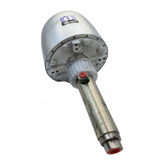
43:1 Bulldog
Hydraulic Supply
Pump
Supplies hydraulic oil to the accumulators in an oil rig blow-out prevention system.
Model 218334, Series A
4300 psi (301 bar, 30.1 MPa) Maximum Working Pressure
Important Safety Instructions
Read all warnings and instructions in this
manual. Save these instructions.
307714E
EN
Advertisement
Table of Contents

Related Manuals for Graco 218334


Summary of Contents for Graco 218334
- Page 1 Hydraulic Supply Pump 307714E Supplies hydraulic oil to the accumulators in an oil rig blow-out prevention system. Model 218334, Series A 4300 psi (301 bar, 30.1 MPa) Maximum Working Pressure Important Safety Instructions Read all warnings and instructions in this...
- Page 2 Warnings Warnings The following warnings are for the setup, use, grounding, maintenance, and repair of this equipment. The exclamation point symbol alerts you to a general warning and the hazard symbols refer to procedure-specific risks. When these symbols appear in the body of this manual or on warning labels, refer back to these Warnings. Product-specific hazard symbols and warnings not covered in this section may appear throughout the body of this manual where applicable.
- Page 3 Warnings WARNING WARNING WARNING WARNING EQUIPMENT MISUSE HAZARD Misuse can cause death or serious injury. • Do not operate the unit when fatigued or under the influence of drugs or alcohol. • Do not exceed the maximum working pressure or temperature rating of the lowest rated system com- ponent.
-
Page 4: Typical Installation
Typical Installation Typical Installation Grounded Air Supply Line Air Filter Air Line Oiler Bleed-Type Master Air Valve Air Regulator Air Inlet Fluid Outlet Grounded Fluid Line Fluid Inlet Grounded Fluid Supply Line Fluid Reservoir Fluid Drain Valve 307714E... -
Page 5: Installation
The Typical Installation shown in F . 1, page 4 is only a guide. Contact your Graco representative for assistance in designing a system to meet your needs. Mount the pump to suit your type of installation. The Dimension Drawing on page 18 gives measurements needed for installing the pump. -
Page 6: System Accessories
Installation System Accessories • ALL FLUID HOSES MUST HAVE SPRING GUARDS! The spring guards help protect the hose from kinks or bends at or close to the coupling which The following instructions refer Typical Installation, F can result in hose rupture. 1, page 4. -
Page 7: Operation
Operation Operation NOTICE Never allow the pump to run dry of fluid being pumped. A dry pump will quickly accelerate to a high speed, pos- Never exceed 100 psi (7 bar, 0.7 MPa) air input sibly damaging itself. pressure to the pump, to reduce the risk of component rupture which can cause serious bodily •... -
Page 8: Maintenance And Repair
Maintenance and Repair Maintenance and Repair Air Leak Check Chart Stroke Check Points Checking Cause Position . 3) Method Blown air manifold A - air manifold By feel gasket (91) Never operate the pump with the air motor shield B - between Blown air cylinder By feel Down... -
Page 9: Fluid Leaks
Maintenance and Repair Fluid Leaks Air Motor Disassembly Reference numbers used in the following instructions If the pump continues to operate when the hydraulic out- refer to F . 4 on page 10. let valve is closed, the packings are worn or the ball check valves are leaking. - Page 10 NOTE: Special care to avoid damaging the plated surface of the trip rod must be taken. A padded pli- ers, part number 207579 is available from Graco. 16. Remove the thrust washer (96) and dampening pad (97) from the air motor cylinder (104).
-
Page 11: Air Motor Assembly
NOTE: Special care to avoid damaging the plated surface of the trip rod must be taken. A padded pli- 24. Reinstall the swivel adapter (117). Screw in the lift ers, part number 207579 is available from Graco. ring (74). 307714E... -
Page 12: Displacement Pump Service
Maintenance and Repair Displacement Pump Service piece. Do NOT break loose the epoxy fitting. NOTE: Replacing this assembly requires disassem- Pump Disassembly bly of the air motor, as described in the previous section. Reference numbers used in the following instructions refer to F . - Page 13 Maintenance and Repair 6. Place the check ball (48) onto the seat of the piston 10. Place the ball stop pin (58) into the upper set of the and valve seat housing (54) and screw the housing holes of the ball guide (59). into the piston shaft (45).
- Page 14 Parts Parts See detail, page 13 lips of v-packings must face up Torque to 20-25 ft-lbs (27-34 N.m) Torque to 25 ft-lbs (34 N.m) Apply sealant and toque to 137-143 ft-lbs (186-194 N.m) 307714E...
- Page 15 Parts Parts Ref. Part Description Qty. 161559 WASHER, backup; leather Ref. Part Description Qty. 150647 GASKET, brass 168184 SEAL, valve plate 169584 PLATE, valve 218596 ROD, trip and piston assembly 161585 HOUSING, air valve 218598 ROD, trip 161556 GASKET 177080 PISTON, air motor 177486 CYLINDER, air motor 215916 SHAFT, piston 100424 CAPSCREW, hex head;...
-
Page 16: Kits And Accessories
Kits and Accessories Kits and Accessories Air Pressure Regulator Grounding Clamp and Wire 300 psi (21 bar, 2.1 MPa) Maximum Working Pressure Ref Part No. Description Part No. Description a 103538 Grounding Clamp b 222011 Ground Wire 206197 1/2 npt inlet and outlet 207755 3/4 npt inlet and outlet Air Line Filter Air Line Lubricator... - Page 17 Kits and Accessories Dimensions Diameter 11 in. (279.4 mm) Air Inlet 3/4 npsm Weep Hole - NOTE: Fluid fitting is 90° from weep hole Fluid Outlet 3/4 npt 10.5 in. (266.7 mm) 29.5 in. (0.75 m) 14.7 in. (373.4 mm) Fluid Intake 1 in.
-
Page 18: Technical Data
Technical Data Technical Data 43:1 Bulldog Hydraulic Supply Pump Metric Maximum working pressure 4300 psi 30.1 MPa, 301 bar Maximum air input pressure 100 psi 0.7 MPa, 7 bar Air inlet 3/4 npsm(f) Fluid inlet 1 in. npt(f) Fluid outlet 3/4 npt(f) Materials of Construction Wetted materials on all models... - Page 19 Notes Notes 307714E...
-
Page 20: Graco Standard Warranty
With the exception of any special, extended, or limited warranty published by Graco, Graco will, for a period of twelve months from the date of sale, repair or replace any part of the equipment determined by Graco to be defective.
Need help?
Do you have a question about the 218334 and is the answer not in the manual?
Questions and answers