EK-Quantum Vector2 Strix TUF RTX 3090 Ti ABP Set D-RGB User Manual
Gpu water block
Hide thumbs
Also See for Vector2 Strix TUF RTX 3090 Ti ABP Set D-RGB:
- User manual (23 pages) ,
- Manual (21 pages) ,
- Quick start manual (16 pages)
Table of Contents
Advertisement
Quick Links
Advertisement
Table of Contents

Subscribe to Our Youtube Channel
Related Manuals for EK-Quantum Vector2 Strix TUF RTX 3090 Ti ABP Set D-RGB


Summary of Contents for EK-Quantum Vector2 Strix TUF RTX 3090 Ti ABP Set D-RGB
- Page 1 EK-Quantum Vector² Strix/TUF RTX 3090 Ti ABP Set D-RGB GPU WATER BLOCK USER GUIDE...
- Page 2 Please note the installation of the product is intended to be undertaken by an adequately trained and experienced person. You are installing the product at your own risk. If you are not properly trained or experienced or feel unsure about the installation procedure, please refrain from installing the product yourself and contact our tech support for assistance.
-
Page 3: Table Of Contents
TABLE OF CONTENTS BOX CONTENTS WATER BLOCK DIMENSIONS TECHNICAL SPECIFICATIONS AND WATER BLOCK PARTS NICKEL PLEXI PREPARING THE GRAPHICS CARD REMOVING THE STOCK LIQUID COOLER FROM STRIX RTX 3090 TI REMOVING THE STOCK LIQUID COOLER FROM TUF RTX 3090 TI CLEANING THE PCB PREPARING THE WATER BLOCK FOR INSTALLATION CUTTING AND PLACING THERMAL PADS... -
Page 4: Box Contents
BOX CONTENTS EAN: 105526 EK-Quantum Vector Strix/TUF RTX 3090 Ti ABP Set D-RGB M3 x 6 DIN7991 Screw (2 pc) M2.5x4 AX1 Screw (8 pcs) M2.5x6 AX1 Screw (1 pc) Nut M2.5 (2 pcs) M3x10 AX1 Screw (1 pc) Polyamid Washer M2.5 0.5mm (8 pcs) Strix/TUF Double Slot Bracket (1 pc) Standoff Ø4.5/2.5 (1 pc) -
Page 5: Water Block Dimensions
WATER BLOCK DIMENSIONS 41 mm 35.5 mm - 5 -... -
Page 6: Technical Specifications And Water Block Parts
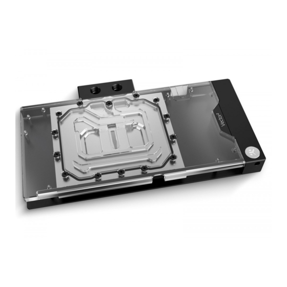
TECHNICAL SPECIFICATIONS AND WATER BLOCK PARTS NICKEL PLEXI - Dimensions: (L x H x W): 307.15 x 155 x 41mm - D-RGB LED count: 30 - D-RGB cable length: 50 cm - D-RGB connector 3-pin 5V digital LED header Position Description Quantity 105518... -
Page 7: Preparing The Graphics Card
PREPARING THE GRAPHICS CARD STEP 1 For this step, you will need: Phillips Head Screwdriver REMOVING THE STOCK LIQUID COOLER FROM STRIX RTX 3090 Ti Use the Phillips head screwdriver to remove the thirteen (13) marked stock screws from the backside of the GPU. Two (2) screw positions, marked red need to be detached from the front side of the stock cooler. -
Page 8: Removing The Stock Liquid Cooler From Tuf Rtx 3090 Ti
REMOVING THE STOCK LIQUID COOLER FROM TUF RTX 3090 Ti Use the Phillips head screwdriver to remove the fifteen (15) marked stock screws from the backside of the GPU. To uninstall the cooler you will have to remove the eigth (8) stock screws from the bracket. -
Page 9: Preparing The Water Block For Installation
PREPARING THE WATER BLOCK FOR INSTALLATION STEP 1 DO NOT M3 x 10 AX1 SCREW First, remove the terminal badge which is attached to the REMOVE terminal with two magnets. Under the badge, unscrew three (3) THE UPPER screws M4 x 20 DIN7984. Additional seven (7) screws M3 x 10 TERMINAL AX1 need to be removed (as shown in the image). - Page 10 EK-Plug Out Spludger Tool M3.5-M2.5 x 11.3 STANDOFF STEP 3 STEP 4 EK-Quantum Vector Strix/TUF RTX 3090 Ti D-RGB - Nickel + Plexi M3 x 6 DIN7991 comes with it’s own custom Double Slot Bracket. Position the SCREW bracket accordingly and use Allen Key to screw in two (2) M3 x 6 DIN7991 Screws.
-
Page 11: Cutting And Placing Thermal Pads
CUTTING AND PLACING THERMAL PADS Your EK-Quantum Vector Strix/TUF RTX 3090 Ti D-RGB block comes Thermal Pad F – 1.0 mm (120 x 16 mm) with Thermal Pads that have to be cut into smaller pieces to cover all the VRM components. EK made sure to provide you with more than an adequate quantity of Thermal Pads to complete this Step. -
Page 12: Applying Thermal Compound
APPLYING THERMAL COMPOUND STEP 1 Apply the enclosed EK-TIM Ectotherm thermal grease (thermal compound) on the GPU heat spreader – IHS – as shown in the image. The layer of the thermal compound must be thin and even over the entire surface of the IHS. The excessive or uneven application of thermal grease may lead to poor performance! For this step, you will need:... - Page 13 STEP 2 After placing the water block, use six (6) M2.5 x 4 AX1 screws and M2.5 x 6 AX1 SCREW PVC washers to tighten the GPU PCB. Tighten the screws evenly using the Phillips-head screwdriver. EK recommends you start tightening the screws around the GPU core first and then continuing M2.5 x 4 AX1 SCREW outward to prevent damaging the GPU.
- Page 14 STEP 3 Place the M2.5-M3 x 6.6 Standoff in each of the seven (7) mounting holes of the standoff M3.5-M2.5 x 11.3 (as shown in the image) M2.5-M3 x 6.6 STANDOFF and tighten them evenly with the EK-Plug-Out Spludger Tool. Do not use excessive force! For this step, you will need: EK-Plug Out Spludger Tool...
-
Page 15: Preparing The Backplate
PREPARING THE BACKPLATE STEP 1 After attaching the water block, a few more thermal pads need to be Thermal Pad F – 1.0 mm (120 x 16 mm) placed on the backside of the GPU PCB. Once cut to size, thermal pads should be placed on the PCB, as illustrated. - Page 16 STEP 2 Put two O-rings 14 x 1 into slots on the cold plate. Then carefully ACTIVE place the active backplate on standoffs as shown in the image. While BACKPLATE putting the active backplate on the PCB, make sure the O-rings stay in the slots.
-
Page 17: Fittings And Tubing
FITTINGS AND TUBING STEP 1 Screw-in two (2) G1/4 threaded male fittings. Attach the liquid cooling tubes and connect the water block to the cooling loop. EK-FITTING Do not forget to plug the remaining two openings with enclosed EK-Plug G1/4 or its equivalent. EK recommends using EK fittings with all EK water blocks. -
Page 18: Connecting The D-Rgb Led Strip
CONNECTING THE D-RGB LED STRIP STEP 1 Plug the 3-pin connector of the distribution plate D-RGB LED light to the D-RGB HEADER on the motherboard. The LED will work if the pin layout on the header is as follows: +5V, Digital, Empty, Ground. -
Page 19: Warranty
WARRANTY Our products are warranted against defects of materials and quality for a period of 24 months, starting with the date of delivery to the end-user. During this period, products will be repaired or have parts replaced at our discretion, provided that 1) the product is returned to the agent from whom it was purchased;... -
Page 20: Support And Service
SUPPORT AND SERVICE In case you need assistance or wish to order spare parts or a new mounting mechanism, please contact: https://www.ekwb.com/customer-support/ For spare parts orders, refer to the page with “TECHNICAL SPECIFICATIONS AND WATER BLOCK PARTS” where you can find the EAN number of each part you might need.
Need help?
Do you have a question about the Vector2 Strix TUF RTX 3090 Ti ABP Set D-RGB and is the answer not in the manual?
Questions and answers