Advertisement
Available languages
Available languages
EVCO S.p.A. | EVD EXP | Instruction sheet ver. 1.0 | Code 104DEXPA103 | Page 1 of 2 | PT 20/17
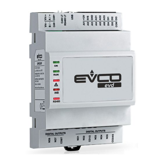
EVD EXP
EN
ENGLISH
-
115... 230 VAC insulated
-
7 analogue inputs (can be configured also for dry contact digital input)
-
3 dry contact digital inputs
-
2 analogue outputs
-
4 electro-mechanical relay digital outputs
-
1 open collector output
-
INTRABUS port.
1
MEASUREMENTS AND INSTALLATION
Measurements in mm (inches). To be fitted on a DIN rail, in a control panel.
To install the device operate as shown in pictures 1 and 2.
To remove the device, first remove any screw-in removable terminal blocks mounted in the
lower part, then operate as shown in pictures 3 and 4.
To install the device again press down the clip before.
INSTALLATION PRECAUTIONS
The DIN rail size must be 35.0 x 7.5 mm (1 3/8 x 5/16) or 35.0 x 15.0 mm (1 3/8 x
-
9/16)
Ensure that the working conditions are within the limits stated in the TECHNICAL
-
SPECIFICATIONS section
Do not install the device close to heat sources, equipment with a strong magnetic field,
-
in places subject to direct sunlight, rain, damp, excessive dust, mechanical vibrations
or shocks
-
In compliance with safety regulations, the device must be installed properly to ensure
adequate protection from contact with electrical parts. All protective parts must be
fixed in such a way as to need the aid of a tool to remove them.
2
ELECTRICAL CONNECTION
N.B.
- Use cables of an adequate section for the current running through them
- To reduce any electromagnetic interference connect the power cables as far away
as possible from the signal cables and, if necessary, connect to an INTRABUS net-
work by using a twisted pair. We recommend using a BELDEN 3106A cable
I/O expansion for parametric controllers
2.1
Connectors
Description of connectors.
Connector 1
No.
DESCRIPTION
1
DO1 digital output normally open contact (3 A res. @ 250 VAC)
2
DO2 digital output normally open contact (3 A res. @ 250 VAC)
3
DO1 and DO2 digital outputs common contact
Connector 2
No.
DESCRIPTION
1
DO3 digital output normally open contact (12 A res. @ 250 VAC)
2
DO3 and DO4 digital outputs common contact
3
DO3 and DO4 digital outputs common contact
4
DO4 digital output normally open contact (8 A res. @ 250 VAC)
5
DO4 digital output normally closed contact (8 A res. @ 250 VAC)
Connector 3
No.
DESCRIPTION
7
device power supply (115... 230 VAC)
8
device power supply (115... 230 VAC)
Connector 4
No.
DESCRIPTION
1
analogue output AO2
2
analogue output AO1
3
reference (GND)
4
analogue input IN1
5
digital input IN10 (dry contact)
6
analogue input IN2
7
digital input IN9 (dry contact and for pulse trains)
8
analogue input IN3
9
digital input IN8 (dry contact and for pulse trains)
10
analogue input IN4
11
analogue input IN7
12
analogue input IN5
13
reference (GND)
14
analogue input IN6
15
reserved
16
auxiliary power supply (12 VDC, max. 40 mA)
17
OC1 open collector output (12 V, max. 40 mA)
18
reference (GND)
Connector 5
No.
DESCRIPTION
1
reference (GND)
2
INTRABUS port data
3
power supply EV3K11 or EVJ LCD (12 VDC)
2.2
Electrical connection
Example of electrical connection.
PRECAUTIONS FOR ELECTRICAL CONNECTION
If using an electrical or pneumatic screwdriver, adjust the tightening torque
-
If the device has been moved from a cold to a warm place, the humidity may have
-
caused condensation to form inside. Wait about an hour before switching on the power
-
Make sure that the supply voltage, electrical frequency and power are within the set
limits. See the section TECHNICAL SPECIFICATIONS
Disconnect the power supply before doing any type of maintenance
-
-
The devices must be fed by power of the same phase as that feeding any module with
a phase-cutting command signal
-
Do not use the device as safety device
-
For repairs and for further information, contact the EVCO sales network.
3
TECHNICAL SPECIFICATIONS
Purpose of the control device:
Function controller.
Construction of the control device:
Built-in electronic device.
Container:
Grey, self-extinguishing.
Category of heat and fire resistance:
D.
Measurements:
71.0 x 168.0 x 60.0 mm (2 13/16 x 6 5/8 x
2 3/8 in). 4 DIN modules.
Mounting methods for the control device:
To be fitted on a DIN rail, in a control panel.
The DIN rail must be 35.0 x 7.5 mm (1 3/8 x
5/16) or 35.0 x 15.0 mm (1 3/8 x 9/16)
Degree of protection provided by the cover-
IP40 (front).
ing:
Connection method:
Micro-Fit connector
Plug-in screw terminal blocks.
Maximum permitted length for connection cables:
Power supply: 10 m (32.8 ft)
Analogue inputs: 10 m (32.8 ft)
Auxiliary power supply: 10 m (32.8 ft)
Digital inputs: 10 m (32.8 ft)
0-10 V and phase cutting analogue outputs:
PWM analogue outputs: 1 m (3.28 ft)
10 m (32.8 ft)
Digital outputs: 10 m (32.88 ft)
INTRABUS port: 10 m (32.8 ft).
To cable the device, we recommend using the CJAV38 connection kit (to be ordered sepa-
rately).
Operating temperature:
From -10 to 55 °C (from 14 to 131 °F).
Storage temperature:
From -20 to 70 °C (from -4 to 158 °F).
Operating humidity:
Relative humidity without condensate from 5
to 95%.
Pollution status of the control device:
2.
Compliance:
RoHS 2011/65/EC
WEEE 2012/19/EU
REACH (EC) Regulation no. 1907/2006
EMC 2014/30/EU.
Power supply:
115... 230 VAC (+10% -15%), 50/60 Hz
(±3 Hz), max. 6 VA insulated.
Protect the power supply with a 2 A-T 250 VAC fuse.
Earthing methods for the control device:
None.
Rated impulse-withstand voltage:
4 KV.
Over-voltage category:
II.
Software class and structure:
A.
Analogue inputs:
5 for NTC probes (can be configured also for
dry contact digital input)
2 for NTC probes, 0-10 V or 4-20 mA trans-
ducers (can be configured also for dry contact
digital input).
NTC probes:
Sensor type:
ß3435 (10 K @ 25 °C, 77 °F)
Measurement field:
from -50 to 120 °C (from -58 to 248 °F)
Resolution:
0.1 °C (1 °F).
Input resistance:
> 10 K
0-10 V trans-
ducers:
Resolution:
0.1 V.
4-20
mA
Input resistance:
≤ 200
transducers:
Resolution:
0.01 mA.
Auxiliary power supply:
12 VDC, 40 mA max.
Digital inputs:
2 dry contact and for pulse trains
1 dry contact.
Dry contact:
Contact type:
Power supply:
Analogue outputs:
2 for 0-10 V, PWM or phase cutting signal.
0-10
V sig-
Minimum applicable imped-
1 K
nal:
ance:
Resolution:
0.01 V.
Power supply:
0... 10 VDC (+16% -25%), 10 mA max.
PWM signal:
Frequency:
10 Hz... 2 KHz
Duty:
0... 100%.
Digital outputs:
4 electro-mechanical relay:
- 2 SPST 3 A res. @ 250 VAC
- 1 SPST 12 A res. @ 250 VAC
- 1 SPDT 8 A res. @ 250 VAC
1 open collector (12 V, max. 40 mA).
Type 1 or Type 2 Actions:
Type 1.
Additional features of Type 1 or Type 2 ac-
C.
tions:
Displays:
Signaling LEDs.
Communications ports:
1 INTRABUS port.
3.3 VDC, 1 mA
None.
Advertisement
Table of Contents

Subscribe to Our Youtube Channel
Related Manuals for Evco EVD EXP


Summary of Contents for Evco EVD EXP
- Page 1 EVCO S.p.A. | EVD EXP | Instruction sheet ver. 1.0 | Code 104DEXPA103 | Page 1 of 2 | PT 20/17 EVD EXP I/O expansion for parametric controllers Connectors TECHNICAL SPECIFICATIONS Purpose of the control device: Function controller. Construction of the control device: Built-in electronic device.
- Page 2 EVCO S.p.A. | EVD EXP | Instruction sheet ver. 1.0 | Code 104DEXPA103 | Page 2 of 2 | PT 20/17 ITALIANO Collegamento elettrico alimentazione 115... 230 VAC isolata Esempio di collegamento elettrico. 7 ingressi analogici (configurabili anche per ingresso digitale a contatto pulito)
Need help?
Do you have a question about the EVD EXP and is the answer not in the manual?
Questions and answers